Information injection-pump assembly
ZEXEL
106671-3570
1066713570
HINO
220201860A
220201860a

Rating:
Cross reference number
ZEXEL
106671-3570
1066713570
HINO
220201860A
220201860a
Zexel num
Bosch num
Firm num
Name
Calibration Data:
Adjustment conditions
Test oil
1404 Test oil ISO4113 or {SAEJ967d}
1404 Test oil ISO4113 or {SAEJ967d}
Test oil temperature
degC
40
40
45
Nozzle and nozzle holder
105780-8140
Bosch type code
EF8511/9A
Nozzle
105780-0000
Bosch type code
DN12SD12T
Nozzle holder
105780-2080
Bosch type code
EF8511/9
Opening pressure
MPa
17.2
Opening pressure
kgf/cm2
175
Injection pipe
Outer diameter - inner diameter - length (mm) mm 8-3-600
Outer diameter - inner diameter - length (mm) mm 8-3-600
Overflow valve (drive side)
134424-1420
Overflow valve opening pressure (drive side)
kPa
162
147
177
Overflow valve opening pressure (drive side)
kgf/cm2
1.65
1.5
1.8
Overflow valve (governor side)
134424-1720
Overflow valve opening pressure (governor side)
kPa
162
147
177
Overflow valve opening pressure (governor side)
kgf/cm2
1.65
1.5
1.8
Tester oil delivery pressure
kPa
157
157
157
Tester oil delivery pressure
kgf/cm2
1.6
1.6
1.6
Direction of rotation (viewed from drive side)
Right R
Right R
Injection timing adjustment
Direction of rotation (viewed from drive side)
Right R
Right R
Injection order
1-4-2-6-
3-5
Pre-stroke
mm
4.5
4.4
4.5
Beginning of injection position
Drive side NO.1
Drive side NO.1
Difference between angles 1
Cal 1-4 deg. 60 59.5 60.5
Cal 1-4 deg. 60 59.5 60.5
Difference between angles 2
Cyl.1-2 deg. 120 119.5 120.5
Cyl.1-2 deg. 120 119.5 120.5
Difference between angles 3
Cal 1-6 deg. 180 179.5 180.5
Cal 1-6 deg. 180 179.5 180.5
Difference between angles 4
Cal 1-3 deg. 240 239.5 240.5
Cal 1-3 deg. 240 239.5 240.5
Difference between angles 5
Cal 1-5 deg. 300 299.5 300.5
Cal 1-5 deg. 300 299.5 300.5
Injection quantity adjustment
Adjusting point
A
Rack position
7.5
Pump speed
r/min
800
800
800
Average injection quantity
mm3/st.
101
99
103
Max. variation between cylinders
%
0
-2
2
Basic
*
Fixing the lever
*
Injection quantity adjustment_02
Adjusting point
B
Rack position
5.3+-0.5
Pump speed
r/min
360
360
360
Average injection quantity
mm3/st.
10
7
13
Max. variation between cylinders
%
0
-15
15
Fixing the rack
*
Injection quantity adjustment_03
Adjusting point
C
Rack position
10.5
Pump speed
r/min
100
100
100
Average injection quantity
mm3/st.
140
130
150
Fixing the lever
*
Rack limit
*
Timer adjustment
Pump speed
r/min
(925)
Advance angle
deg.
0.3
Timer adjustment_02
Pump speed
r/min
1000
Advance angle
deg.
0.8
0.3
1.3
Timer adjustment_03
Pump speed
r/min
-
Advance angle
deg.
2.5
2.2
2.8
Remarks
Measure the actual speed, stop
Measure the actual speed, stop
Test data Ex:
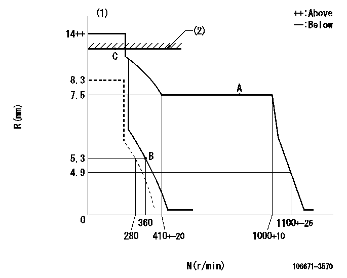
Governor adjustment

N:Pump speed
R:Rack position (mm)
(1)Target notch: K
(2)RACK LIMIT: RAL
----------
K=10 RAL=10.5+-0.1mm
----------
----------
K=10 RAL=10.5+-0.1mm
----------
Speed control lever angle

F:Full speed
I:Idle
----------
----------
a=8deg+-5deg b=17deg+-5deg
----------
----------
a=8deg+-5deg b=17deg+-5deg
Stop lever angle

N:Pump normal
S:Stop the pump.
----------
----------
a=27deg+-5deg b=53deg+-5deg
----------
----------
a=27deg+-5deg b=53deg+-5deg
0000001501 LEVER

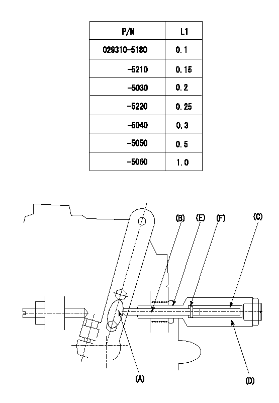
(F) P/N: Part number of the shim
L1:Thickness (mm)
1. Adjustment of the control lever
(1)Perform idling with the control lever (A) contacting the pushrod (B). At this time, confirm that the spring (C) is not compressed by control lever (A)'s operating torque.
(2)To set the stop position, compress spring (C) using the control lever (A) and adjust the rack so that it contacts the guide screw (D) at position L2. Then, set and fix using the lock nut (E). Adjust the rack position L2 at this time using the shim (F).
(3)Confirm that the control lever (A) returns to the idling position when pulled in the stop direction and then released.
----------
L2=0.2~2mm
----------
----------
L2=0.2~2mm
----------
Timing setting

(1)Pump vertical direction
(2)Coupling's key groove position at No 1 cylinder's beginning of injection
(3)-
(4)-
----------
----------
a=(40deg)
----------
----------
a=(40deg)
Information:
If equipped, the PEEC system is capable of being programmed for several customer specified parameters. These parameters are generally programmed so the vehicle will achieve optimum fuel efficiency and operator convenience.The standard engine includes the features of programmable low idle and top engine limiting (TEL). Cruise control, PTO governing, vehicle speed limiting, low and high gears engine rpm limiting (progressive shift control), retarder coast/latch and idle shutdown timer are also available depending on OEM truck configurations.Low idle and top engine rpm limits are customer programmable to promote maximum fuel efficiency. The 3406B PEEC system allows the owner to select power ratings within a "family" to more efficiently match the vehicle to the application.The customer specified parameters and a brief explanation of each are as follows:1. Engine Power Rating - The 3406B PEEC engine is designed to provide full rated power over a large range of engine speeds. For example, the Caterpillar 3406B PEEC Truck Engine ratings for the 1991 1 are: * 310 hp (231 kw) @ 1800 rpm* 310 hp (231 kw) @ 1900 rpm* 330 hp (246 kW) @ 1800 rpm* 350 hp (261 kW) @ 1800 rpm* 350 hp (261 kW) @ 1800 rpm (Multi-torque)* 400 hp (298 kW) @ 1800 rpm* 425 hp (317 kW) @ 1800 rpm* 425 hp (317 kW) @ 1900 rpm* 460 hp (343 kW) @ 1800 rpm* 350 hp (261 kW) @ 2000 rpm* 400 hp (298 kW) @ 2000 rpm* 425 hp (317 kW) @ 2000 rpm* 460 hp (343 kw) @ 1900 rpm*Since EPA, CARB and Canadian emission regulations are identical for 1990 and 1991, no 49-state ratings are required. 2. Vehicle Identification Number - The owner's description, or unit number of the vehicle. 3. PTO Vehicle Speed Limit (PTO VSL) - Maximum vehicle speed at which the PTO Governor will function.4. PTO Engine RPM Limit (PTO RPM) - Maximum engine rpm attainable using the CRUISE CONTROL switches while the vehicle is operated below the PTO VSL (generally used for maximum rpm limit for overnight idling). 5. Low Gears #1 RPM Limit (LoGr #1) - The rpm at which the engine is limited in the lowest gears.6. Low Gears #2 RPM Limit (LoGr #2) - The rpm at which the engine is limited in a secondary gear range.7. Low Gears Turn Off Speed (LoGr Off Limits) - The vehicle speeds at which LoGr #1 and LoGr #2 turn off. 8. High Gears rpm Limit (HiGr rpm) - The rpm at which the engine is limited in the higher gears (generally used to encourage shifting into higher gears).9. High Gear Turn On Speed (HiGr On) - The vehicle speed at which High Gear rpm is in effect.10. Top Engine Limit (TEL) - Maximum allowable engine rpm generally set at rated rpm [rpm at which maximum power is developed] plus (+) 20 rpm. 11. Engine rpm at Vehicle Speed Limit (Eng rpm at VSL) - The engine rpm achieved in high (top) gear at VSL. Interruption of the