Information injection-pump assembly
ZEXEL
106671-3460
1066713460
HINO
220201600A
220201600a
Rating:
Cross reference number
ZEXEL
106671-3460
1066713460
HINO
220201600A
220201600a
Zexel num
Bosch num
Firm num
Name
Calibration Data:
Adjustment conditions
Test oil
1404 Test oil ISO4113 or {SAEJ967d}
1404 Test oil ISO4113 or {SAEJ967d}
Test oil temperature
degC
40
40
45
Nozzle and nozzle holder
105780-8140
Bosch type code
EF8511/9A
Nozzle
105780-0000
Bosch type code
DN12SD12T
Nozzle holder
105780-2080
Bosch type code
EF8511/9
Opening pressure
MPa
17.2
Opening pressure
kgf/cm2
175
Injection pipe
Outer diameter - inner diameter - length (mm) mm 8-3-600
Outer diameter - inner diameter - length (mm) mm 8-3-600
Overflow valve
134424-0920
Overflow valve opening pressure
kPa
162
147
177
Overflow valve opening pressure
kgf/cm2
1.65
1.5
1.8
Tester oil delivery pressure
kPa
157
157
157
Tester oil delivery pressure
kgf/cm2
1.6
1.6
1.6
Direction of rotation (viewed from drive side)
Left L
Left L
Injection timing adjustment
Direction of rotation (viewed from drive side)
Left L
Left L
Injection order
1-4-2-6-
3-5
Pre-stroke
mm
3.3
3.2
3.3
Beginning of injection position
Drive side NO.1
Drive side NO.1
Difference between angles 1
Cal 1-4 deg. 60 59.5 60.5
Cal 1-4 deg. 60 59.5 60.5
Difference between angles 2
Cyl.1-2 deg. 120 119.5 120.5
Cyl.1-2 deg. 120 119.5 120.5
Difference between angles 3
Cal 1-6 deg. 180 179.5 180.5
Cal 1-6 deg. 180 179.5 180.5
Difference between angles 4
Cal 1-3 deg. 240 239.5 240.5
Cal 1-3 deg. 240 239.5 240.5
Difference between angles 5
Cal 1-5 deg. 300 299.5 300.5
Cal 1-5 deg. 300 299.5 300.5
Injection quantity adjustment
Adjusting point
A
Rack position
9.2
Pump speed
r/min
900
900
900
Average injection quantity
mm3/st.
112
109
115
Max. variation between cylinders
%
0
-4
4
Fixing the rack
*
Injection quantity adjustment_02
Adjusting point
B
Rack position
9.5
Pump speed
r/min
750
750
750
Average injection quantity
mm3/st.
121
119
123
Max. variation between cylinders
%
0
-4
4
Basic
*
Fixing the lever
*
Injection quantity adjustment_03
Adjusting point
C
Rack position
6.2+-0.5
Pump speed
r/min
360
360
360
Average injection quantity
mm3/st.
16
13
19
Max. variation between cylinders
%
0
-15
15
Fixing the rack
*
Timer adjustment
Pump speed
r/min
(700+-50
)
Advance angle
deg.
0
0
0
Remarks
Start
Start
Timer adjustment_02
Pump speed
r/min
900
Advance angle
deg.
1.4
0.9
1.9
Timer adjustment_03
Pump speed
r/min
-
Advance angle
deg.
4
4
4
Remarks
Measure the actual speed, stop
Measure the actual speed, stop
Test data Ex:
Governor adjustment
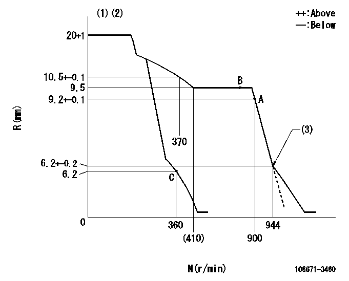
N:Pump speed
R:Rack position (mm)
(1)Target notch: K
(2)Tolerance for racks not indicated: +-0.05mm.
(3)Idle sub spring setting: L1.
----------
K=19 L1=6.2-0.5mm
----------
----------
K=19 L1=6.2-0.5mm
----------
Speed control lever angle

F:Full speed
I:Idle
(1)Stopper bolt setting
----------
----------
a=15deg+-5deg b=20deg+-5deg
----------
----------
a=15deg+-5deg b=20deg+-5deg
Stop lever angle
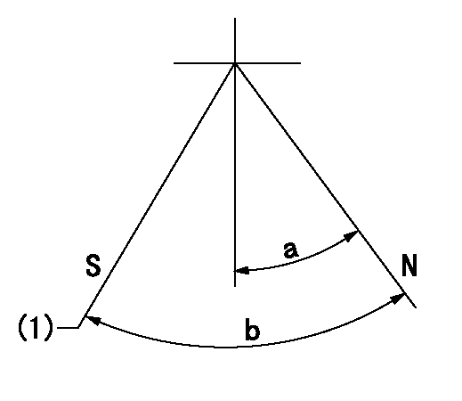
N:Pump normal
S:Stop the pump.
(1)Normal stop
----------
----------
a=38deg+-5deg b=53deg+-5deg
----------
----------
a=38deg+-5deg b=53deg+-5deg
Timing setting

(1)Pump vertical direction
(2)Coupling's key groove position at No 1 cylinder's beginning of injection
(3)-
(4)-
----------
----------
a=(0deg)
----------
----------
a=(0deg)
Information:
Torque For Standard Bolts, Nuts And Taperlock Studs
The following charts give general torques for bolts, nuts and taperlock studs of SAE Grade 5 or better quality.
Torques For Bolts And Nuts With Standard Threads
Torques For Taperlock Studs
Use these standard torque values for all fasteners unless otherwise specified in this publication or in the Service Manual.Torque For Metric Fasteners
Be very careful never to mix metric with customary (standard) fasteners. Mismatched or incorrect fasteners will cause engine damage or malfunction and may even result in personal injury. Original fasteners removed from the engine should be saved for reassembly whenever possible. If new fasteners are needed, they must be of the same size and grade as the ones that are being replaced.The material strength identification is usually shown on the bolt head by numbers (8.8, 10.9, etc.). The following chart gives general torques for bolts and nuts with Grade 8.8.
Torque For Standard Hose Clamps-Worm Drive Band Type
The following chart gives the torques for initial installation of those clamps on new hose and for reassembly or tightening of hose clamps on existing hose.
Constant Torque Hose Clamps
A constant torque hose clamp can be used in place of any standard hose clamp. Make sure the constant torque hose clamp is the same size as the standard clamp.Due to extreme temperature changes, hose will heat set. Heat setting causes hose clamps to loosen. Loose hose clamps can result in leaks. There have been reports of component failures caused by hose clamps loosening. The new, constant torque hose clamp will help prevent these failures.Installation
Each installation application can be different depending on the type of hose, fitting material and anticipated expansion or contraction of the hose and fittings. A torque wrench should be used for proper installation of the new, constant torque hose clamps. Constant torque hose clamps should be installed as follows: To allow for maximum expansion, install clamps at 50 lb in (5.7 N m).To allow for equal expansion and contraction, install clamps at 90 lb in (10.2 N m).To allow for maximum contraction, install clamps at 125 lb in (14.1 N m).