Information injection-pump assembly
ZEXEL
106671-3386
1066713386
HINO
220004080A
220004080a

Rating:
Service parts 106671-3386 INJECTION-PUMP ASSEMBLY:
1.
_
7.
COUPLING PLATE
8.
_
9.
_
11.
Nozzle and Holder
23600-1221
12.
Open Pre:MPa(Kqf/cm2)
21.6{220}

15.
NOZZLE SET
Include in #1:
106671-3386
as INJECTION-PUMP ASSEMBLY
Cross reference number
ZEXEL
106671-3386
1066713386
HINO
220004080A
220004080a
Zexel num
Bosch num
Firm num
Name
Calibration Data:
Adjustment conditions
Test oil
1404 Test oil ISO4113 or {SAEJ967d}
1404 Test oil ISO4113 or {SAEJ967d}
Test oil temperature
degC
40
40
45
Nozzle and nozzle holder
105780-8140
Bosch type code
EF8511/9A
Nozzle
105780-0000
Bosch type code
DN12SD12T
Nozzle holder
105780-2080
Bosch type code
EF8511/9
Opening pressure
MPa
17.2
Opening pressure
kgf/cm2
175
Injection pipe
Outer diameter - inner diameter - length (mm) mm 8-3-600
Outer diameter - inner diameter - length (mm) mm 8-3-600
Overflow valve
134424-0920
Overflow valve opening pressure
kPa
157
123
191
Overflow valve opening pressure
kgf/cm2
1.6
1.25
1.95
Tester oil delivery pressure
kPa
157
157
157
Tester oil delivery pressure
kgf/cm2
1.6
1.6
1.6
Direction of rotation (viewed from drive side)
Left L
Left L
Injection timing adjustment
Direction of rotation (viewed from drive side)
Left L
Left L
Injection order
1-4-2-6-
3-5
Pre-stroke
mm
3.3
3.24
3.3
Beginning of injection position
Drive side NO.1
Drive side NO.1
Difference between angles 1
Cal 1-4 deg. 60 59.75 60.25
Cal 1-4 deg. 60 59.75 60.25
Difference between angles 2
Cyl.1-2 deg. 120 119.75 120.25
Cyl.1-2 deg. 120 119.75 120.25
Difference between angles 3
Cal 1-6 deg. 180 179.75 180.25
Cal 1-6 deg. 180 179.75 180.25
Difference between angles 4
Cal 1-3 deg. 240 239.75 240.25
Cal 1-3 deg. 240 239.75 240.25
Difference between angles 5
Cal 1-5 deg. 300 299.75 300.25
Cal 1-5 deg. 300 299.75 300.25
Injection quantity adjustment
Adjusting point
A
Rack position
10.6
Pump speed
r/min
500
500
500
Average injection quantity
mm3/st.
129
126
132
Max. variation between cylinders
%
0
-4
4
Fixing the lever
*
Injection quantity adjustment_02
Adjusting point
B
Rack position
10.9
Pump speed
r/min
700
700
700
Average injection quantity
mm3/st.
139.5
137.5
141.5
Max. variation between cylinders
%
0
-2
2
Basic
*
Fixing the lever
*
Injection quantity adjustment_03
Adjusting point
C
Rack position
11.4
Pump speed
r/min
1150
1150
1150
Average injection quantity
mm3/st.
148
145
151
Max. variation between cylinders
%
0
-4
4
Fixing the lever
*
Injection quantity adjustment_04
Adjusting point
D
Rack position
7+-0.5
Pump speed
r/min
225
225
225
Average injection quantity
mm3/st.
15
12
18
Max. variation between cylinders
%
0
-15
15
Fixing the rack
*
Injection quantity adjustment_05
Adjusting point
E
Rack position
-
Pump speed
r/min
100
100
100
Average injection quantity
mm3/st.
126.3
119.3
133.3
Fixing the lever
*
Timer adjustment
Pump speed
r/min
1000--
Advance angle
deg.
0
0
0
Remarks
Start
Start
Timer adjustment_02
Pump speed
r/min
950
Advance angle
deg.
0.5
Timer adjustment_03
Pump speed
r/min
1000
Advance angle
deg.
1.5
Timer adjustment_04
Pump speed
r/min
1050
Advance angle
deg.
1.9
1.4
2.4
Timer adjustment_05
Pump speed
r/min
1150
Advance angle
deg.
4.5
4
5
Remarks
Finish
Finish
Test data Ex:
Governor adjustment
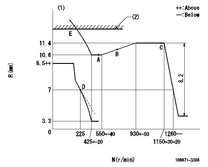
N:Pump speed
R:Rack position (mm)
(1)Beginning of damper spring operation: DL
(2)RACK LIMIT
----------
DL=6.2-0.2mm
----------
----------
DL=6.2-0.2mm
----------
Speed control lever angle

F:Full speed
----------
----------
a=3deg+-5deg
----------
----------
a=3deg+-5deg
0000000901
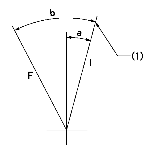
F:Full load
I:Idle
(1)Stopper bolt setting
----------
----------
a=10deg+-5deg b=27.5deg+-3deg
----------
----------
a=10deg+-5deg b=27.5deg+-3deg
Stop lever angle

N:Pump normal
S:Stop the pump.
----------
----------
a=15deg+-5deg b=64deg+-5deg
----------
----------
a=15deg+-5deg b=64deg+-5deg
0000001501 GOVERNOR TORQUE CONTROL

Dr:Torque control stroke
(A): Without torque control spring capsule
1. Adjustment procedures
(1)Procedure is the same as that for the RFD (former type), except that the positive torque control stroke must be determined at the full lever setting.
2. Procedures for adjustment
(1)Remove the torque control spring capsule.
(2)Operate the pump at approximately N1. (End of idling spring operation < N1.)
(3)Tilt the lever to the full side.
(4)Set so that R = RF.
(5)Increase the speed by pushing in the screw (attached to the bracket on the rear of the tension lever) through the adjusting window.
(6)Adjust so that the torque control stroke Dr1 can be obtained.
(7)Align N2 and N3 with the torque control spring capsule.
3. Final confirmation
(1)After final confirmation, temporarily set the load lever to N = N1, R = idling position.
(2)From this condition, increase speed to N = N4.
(3)Confirm that positive torque control stroke is Dr2.
----------
N1=500r/min N2=550+-40r/min N3=930+-50r/min N4=950r/min RF=10.6mm Dr1=0.8mm Dr2=0+0.3mm
----------
----------
N1=500r/min N2=550+-40r/min N3=930+-50r/min N4=950r/min RF=10.6mm Dr1=0.8mm Dr2=0+0.3mm
----------
Information:
USE FUEL CONSUMPTION, SERVICE HOURS OR TIME INTERVAL, WHICHEVER OCCURS FIRST. Performance of all lubrication and maintenance items in the Maintenance Schedule is the owners' responsibility.Daily
Walk-Around Inspection - Inspect for leaks and loose connections Engine Crankcase - Check oil level Cooling System - Check coolant level Air Cleaner Indicator - Test Air Starting Motor (If Equipped) - Check/fill oiler bowlEvery 18 950 L (5000 gal) of Fuel or 125 Hours*
Scheduled Oil Sampling (S O S) Analysis - Obtain sample Engine Oil & Filters - Change oil and oil filter(s) Fuel System - Drain water/sediment Cooling System - Test Crankcase Breathers - Clean Engine Valve Lash (At First Oil Change Only) - Check/AdjustEvery 37 900 L (10,000 gal) of Fuel or 250 Hours*
Batteries - Clean/Check electrolyte level Belts, Hoses and Clamps - Inspect/Replace if necessary Engine Air Cleaners - Replace Engine Speed Sensors - Inspect/clean magnetic pick-upEvery 151 600 L (40,000 gal) of Fuel or 1000 Hours*
Engine Protection Devices - Inspect for proper operation (Check at least twice per year) Engine Valve Lash - Check/Adjust Turbochargers - Inspect for proper operation Engine Mounts and Crankshaft Vibration Damper - Inspect/checkEvery 341 100 L (90,000 gal) of Fuel or 2250 Hours*
Connecting Rod Bearings - ReplaceEvery 454 800 L (120,000 gal) of Fuel or 3000 Hours or Two Years*
Cooling System - Clean/Flush/replace thermostats and gasketsOverhaul Every 511 650 L (135,000 gal) of Fuel or 5400 Hours*
To minimize downtime and provide you with the lowest cost and highest value, Caterpillar recommends that the engine be overhauled before failure by scheduling an overhaul with your Caterpillar dealer. Refer to the Overhaul section in this manual on page 85. Top End Overhaul After Failure Overhaul Starting Motor - Inspect for proper operation Alternator - Inspect for proper operation Engine Speed Sensors - Inspect/clean/test*First Perform Previous Service Hour Items Caterpillar suggests that fuel consumption be used as the preferred method of determining maintenance intervals. Fuel consumption/hours will vary depending on the proper application of your engine rating and adherence to recommended maintenance procedures.