Information injection-pump assembly
ZEXEL
106671-3380
1066713380
HINO
220003561A
220003561a
Rating:
Cross reference number
ZEXEL
106671-3380
1066713380
HINO
220003561A
220003561a
Zexel num
Bosch num
Firm num
Name
Calibration Data:
Adjustment conditions
Test oil
1404 Test oil ISO4113 or {SAEJ967d}
1404 Test oil ISO4113 or {SAEJ967d}
Test oil temperature
degC
40
40
45
Nozzle and nozzle holder
105780-8140
Bosch type code
EF8511/9A
Nozzle
105780-0000
Bosch type code
DN12SD12T
Nozzle holder
105780-2080
Bosch type code
EF8511/9
Opening pressure
MPa
17.2
Opening pressure
kgf/cm2
175
Injection pipe
Outer diameter - inner diameter - length (mm) mm 8-3-600
Outer diameter - inner diameter - length (mm) mm 8-3-600
Overflow valve
134424-0920
Overflow valve opening pressure
kPa
162
147
177
Overflow valve opening pressure
kgf/cm2
1.65
1.5
1.8
Tester oil delivery pressure
kPa
157
157
157
Tester oil delivery pressure
kgf/cm2
1.6
1.6
1.6
Direction of rotation (viewed from drive side)
Left L
Left L
Injection timing adjustment
Direction of rotation (viewed from drive side)
Left L
Left L
Injection order
1-4-2-6-
3-5
Pre-stroke
mm
3.3
3.24
3.3
Beginning of injection position
Drive side NO.1
Drive side NO.1
Difference between angles 1
Cal 1-4 deg. 60 59.75 60.25
Cal 1-4 deg. 60 59.75 60.25
Difference between angles 2
Cyl.1-2 deg. 120 119.75 120.25
Cyl.1-2 deg. 120 119.75 120.25
Difference between angles 3
Cal 1-6 deg. 180 179.75 180.25
Cal 1-6 deg. 180 179.75 180.25
Difference between angles 4
Cal 1-3 deg. 240 239.75 240.25
Cal 1-3 deg. 240 239.75 240.25
Difference between angles 5
Cal 1-5 deg. 300 299.75 300.25
Cal 1-5 deg. 300 299.75 300.25
Injection quantity adjustment
Adjusting point
A
Rack position
10.6
Pump speed
r/min
500
500
500
Average injection quantity
mm3/st.
129
126
132
Max. variation between cylinders
%
0
-4
4
Fixing the lever
*
Injection quantity adjustment_02
Adjusting point
B
Rack position
10.9
Pump speed
r/min
700
700
700
Average injection quantity
mm3/st.
139.5
137.5
141.5
Max. variation between cylinders
%
0
-2
2
Basic
*
Fixing the lever
*
Injection quantity adjustment_03
Adjusting point
C
Rack position
11.3
Pump speed
r/min
1150
1150
1150
Average injection quantity
mm3/st.
148
145
151
Max. variation between cylinders
%
0
-4
4
Fixing the lever
*
Injection quantity adjustment_04
Adjusting point
D
Rack position
7+-0.5
Pump speed
r/min
225
225
225
Average injection quantity
mm3/st.
15
12
18
Max. variation between cylinders
%
0
-15
15
Fixing the rack
*
Injection quantity adjustment_05
Adjusting point
E
Rack position
-
Pump speed
r/min
100
100
100
Average injection quantity
mm3/st.
126.3
119.3
133.3
Fixing the lever
*
Timer adjustment
Pump speed
r/min
950
Advance angle
deg.
0.5
Timer adjustment_02
Pump speed
r/min
1000
Advance angle
deg.
1.5
Timer adjustment_03
Pump speed
r/min
1050
Advance angle
deg.
1.9
1.4
2.4
Timer adjustment_04
Pump speed
r/min
1150
Advance angle
deg.
4.5
4.2
4.8
Remarks
Finish
Finish
Test data Ex:
Governor adjustment
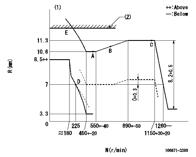
N:Pump speed
R:Rack position (mm)
(1)Beginning of damper spring operation: DL
(2)RACK LIMIT
----------
DL=6.2-0.2mm
----------
----------
DL=6.2-0.2mm
----------
Speed control lever angle

F:Full speed
----------
----------
a=3deg+-5deg
----------
----------
a=3deg+-5deg
0000000901
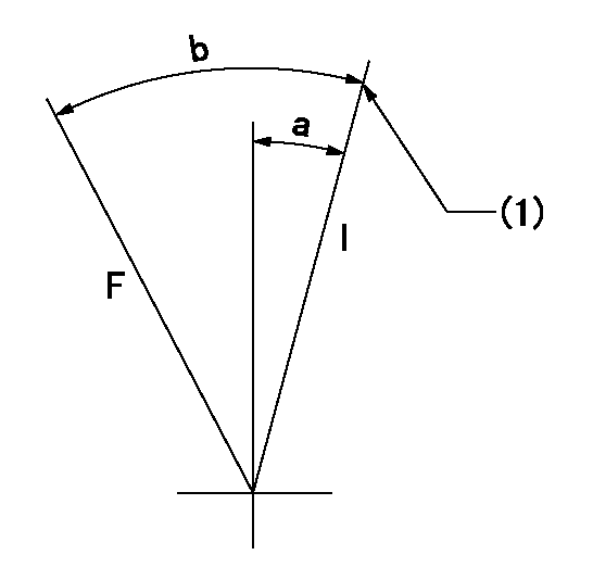
F:Full load
I:Idle
(1)Stopper bolt setting
----------
----------
a=10deg+-5deg b=27.5deg+-3deg
----------
----------
a=10deg+-5deg b=27.5deg+-3deg
Stop lever angle

N:Pump normal
S:Stop the pump.
----------
----------
a=15deg+-5deg b=64deg+-5deg
----------
----------
a=15deg+-5deg b=64deg+-5deg
0000001501 GOVERNOR TORQUE CONTROL
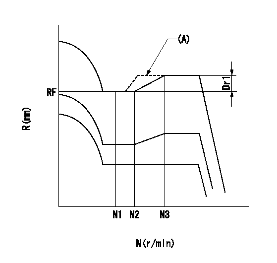
Dr:Torque control stroke
(A): Without torque control spring capsule
1. Adjustment procedures
(1)Procedure is the same as that for the RFD (former type), except that the positive torque control stroke must be determined at the full lever setting.
2. Procedures for adjustment
(1)Remove the torque control spring capsule.
(2)Operate the pump at approximately N1. (End of idling spring operation < N1.)
(3)Tilt the lever to the full side.
(4)Set so that R = RF.
(5)Increase the speed by pushing in the screw (attached to the bracket on the rear of the tension lever) through the adjusting window.
(6)Adjust so that the torque control stroke Dr1 can be obtained.
(7)Align N2 and N3 with the torque control spring capsule.
----------
N1=500r/min N2=550+-40r/min N3=890+-50r/min RF=10.6mm Dr1=0.7mm
----------
----------
N1=500r/min N2=550+-40r/min N3=890+-50r/min RF=10.6mm Dr1=0.7mm
----------
Information:
Refer to the 3408 and 3412 Industrial Engine Troubleshooting Manual for more information.Below 12°C (55°F)
Caterpillar engines are designed to start at temperatures above 12°C (55°F) without using starting aids. If the temperature is below 12°C (55°F), a cylinder block coolant heater may be needed or crankcase oil may need to be heated.At temperatures below 0°C (32°F), it may be necessary to spray starting fluid into the air cleaner inlet. Additional injections of ether may be required to start and/or achieve low idle speed.
When using starting fluid, follow the manufacturer's instructions carefully, use it sparingly and spray it only while cranking the engine. Failure to do so, could result in an explosion and/or fire and possible personal injury.
Excessive ether can cause piston and ring damage. Use ether for cold starting purposes only. Do not use excessive starting fluid during starting or after the engine is running.
* Depress ether aid switch (if equipped with ether injection) and hold for three seconds, then release before performing step 3 above.* Begin cranking engine and depress ether switch and hold for three seconds then release. Additional injections of ether may be required to start and/or achieve low idle speed.The engine will run at low idle and will run smoothly as the electronic control system gradually increases the fuel flow to high idle in the Cold Mode procedure. Low Idle rpm - 600 - 750, Cold Mode rpm - 900 - 1000.Allow white smoke to clear up and proceed with normal operation.For starting below -18°C (0°F), use of optional cold weather starting aids are recommended. A jacket water heater or fuel heater may be required. Consult your Caterpillar dealer for additional information.Starting From External Electrical Source
Make initial determination as to failure of engine to crank. Refer to special instruction SEHS7768 on use of 6V2150 Starting/Charging Analyzer Group.If the installation is not equipped with a back-up battery system, then it may be necessary to start the engine from an external electrical source.Many batteries thought to be unusable, are still rechargeable. Severely discharged maintenance free batteries might not fully recharge from the alternator alone after jump starting. The batteries must be charged to the proper voltage with a battery charger. Refer to Special Instruction, SEHS7633, Battery Test Procedure, available from your Caterpillar dealer, for complete testing and charging information.
Be sure the main power switch is in the OFF position before attaching the booster cables to the engine being started. Turn OFF all electrical accessories.When boost starting an engine, follow the instructions to properly start the engine. This engine is equipped with a 24 volt starting system. Use only equal voltage for boost starting. The use of a welder or higher voltage will damage the electrical system and is not recommended.Do not allow the free ends of jumper cables to touch the engine. This helps avoid sparks. Do not reverse the battery cables. The alternator can be damaged. Attach ground cable last and remove first.
1. When using booster cables, be sure to connect in parallel: Connect