Information injection-pump assembly
ZEXEL
106671-3260
1066713260
HINO
220002170A
220002170a
Rating:
Cross reference number
ZEXEL
106671-3260
1066713260
HINO
220002170A
220002170a
Zexel num
Bosch num
Firm num
Name
Calibration Data:
Adjustment conditions
Test oil
1404 Test oil ISO4113 or {SAEJ967d}
1404 Test oil ISO4113 or {SAEJ967d}
Test oil temperature
degC
40
40
45
Nozzle and nozzle holder
105780-8140
Bosch type code
EF8511/9A
Nozzle
105780-0000
Bosch type code
DN12SD12T
Nozzle holder
105780-2080
Bosch type code
EF8511/9
Opening pressure
MPa
17.2
Opening pressure
kgf/cm2
175
Injection pipe
Outer diameter - inner diameter - length (mm) mm 8-3-600
Outer diameter - inner diameter - length (mm) mm 8-3-600
Overflow valve
134424-0920
Overflow valve opening pressure
kPa
162
147
177
Overflow valve opening pressure
kgf/cm2
1.65
1.5
1.8
Tester oil delivery pressure
kPa
157
157
157
Tester oil delivery pressure
kgf/cm2
1.6
1.6
1.6
Direction of rotation (viewed from drive side)
Left L
Left L
Injection timing adjustment
Direction of rotation (viewed from drive side)
Left L
Left L
Injection order
1-4-2-6-
3-5
Pre-stroke
mm
3.3
3.24
3.3
Beginning of injection position
Drive side NO.1
Drive side NO.1
Difference between angles 1
Cal 1-4 deg. 60 59.75 60.25
Cal 1-4 deg. 60 59.75 60.25
Difference between angles 2
Cyl.1-2 deg. 120 119.75 120.25
Cyl.1-2 deg. 120 119.75 120.25
Difference between angles 3
Cal 1-6 deg. 180 179.75 180.25
Cal 1-6 deg. 180 179.75 180.25
Difference between angles 4
Cal 1-3 deg. 240 239.75 240.25
Cal 1-3 deg. 240 239.75 240.25
Difference between angles 5
Cal 1-5 deg. 300 299.75 300.25
Cal 1-5 deg. 300 299.75 300.25
Injection quantity adjustment
Adjusting point
A
Rack position
9.8
Pump speed
r/min
500
500
500
Average injection quantity
mm3/st.
125.5
122.5
128.5
Max. variation between cylinders
%
0
-4
4
Fixing the lever
*
Injection quantity adjustment_02
Adjusting point
B
Rack position
10.3
Pump speed
r/min
700
700
700
Average injection quantity
mm3/st.
141.2
139.2
143.2
Max. variation between cylinders
%
0
-2
2
Basic
*
Fixing the lever
*
Injection quantity adjustment_03
Adjusting point
C
Rack position
10.7
Pump speed
r/min
1150
1150
1150
Average injection quantity
mm3/st.
149.7
146.7
152.7
Max. variation between cylinders
%
0
-4
4
Fixing the lever
*
Injection quantity adjustment_04
Adjusting point
D
Rack position
5.1+-0.5
Pump speed
r/min
225
225
225
Average injection quantity
mm3/st.
16
13
19
Max. variation between cylinders
%
0
-15
15
Fixing the rack
*
Injection quantity adjustment_05
Adjusting point
E
Rack position
11+-0.5
Pump speed
r/min
100
100
100
Average injection quantity
mm3/st.
125
125
145
Fixing the lever
*
Timer adjustment
Pump speed
r/min
950
Advance angle
deg.
0.5
Timer adjustment_02
Pump speed
r/min
1000
Advance angle
deg.
1.5
Timer adjustment_03
Pump speed
r/min
1050
Advance angle
deg.
1.9
1.4
2.4
Timer adjustment_04
Pump speed
r/min
1150
Advance angle
deg.
4.5
4.2
4.8
Remarks
Finish
Finish
Test data Ex:
Governor adjustment
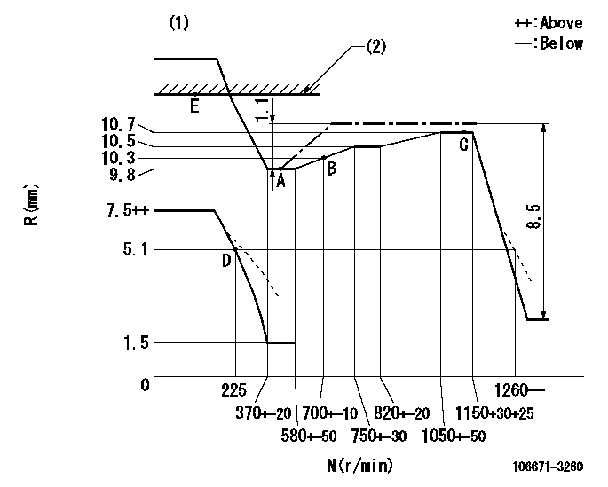
N:Pump speed
R:Rack position (mm)
(1)Beginning of damper spring operation: DL
(2)RACK LIMIT
----------
DL=5.6-0.2mm
----------
----------
DL=5.6-0.2mm
----------
Speed control lever angle

F:Full speed
----------
----------
a=15deg+-5deg
----------
----------
a=15deg+-5deg
0000000901

F:Full load
I:Idle
(1)Stopper bolt setting
----------
----------
a=10deg+-5deg b=29deg+-3deg
----------
----------
a=10deg+-5deg b=29deg+-3deg
Stop lever angle

N:Pump normal
S:Stop the pump.
----------
----------
a=15deg+-5deg b=64deg+-5deg
----------
----------
a=15deg+-5deg b=64deg+-5deg
0000001501 MICRO SWITCH
Switch adjustment
Adjust the bolt so that the lower lever position is obtained when the switch is turned ON.
(1)Speed N1
(2)Rack position Ra
----------
N1=325-25r/min Ra=5.1mm
----------
----------
N1=325-25r/min Ra=5.1mm
----------
Information:
Use quantity of fuel used, distance (odometer) interval or service hours, whichever occurs first.1Experience has shown that maintenance intervals are most accurately scheduled on the basis of fuel consumed. However, Caterpillar recognizes that the distance (odometer) interval is most commonly used to schedule maintenance for on-highway vehicles. Distance intervals are based on a typical over-the-road truck application. For other applications use hours or fuel intervals to determine and schedule maintenance.Daily
Walk-Around Inspection - Inspect engine for leaks and loose connections Engine Crankcase - Check oil level Cooling System - Check coolant level Engine Air Cleaner - Check indicator, clean and replace elements, if necessary Air-to-Air Aftercooler System - Check, clean if necessaryPM Level 1
Every 2,000 gal (7580 L) of Fuel or 12,500 Miles (20 000 km) or 250 Hours* Scheduled Oil Sampling (S O S) Analysis -Obtain Engine Oil and Filter(s)2 - Replace 3 Fuel Filters - Replace final filter and Clean/Replace primary filter (if equipped) 3 Cooling System - Test for concentration/Add coolant additive or Replace supplemental additive element (if equipped) Crankcase Breather - Clean Alternator, Fan and Accessory Drive Belts -Inspect/Replace Hoses and Clamps - Inspect/Replace Air-to-Air Aftercooler System - Inspect/Check Cylinder Head Grounding Stud -Inspect/Clean/Tighten Engine Valve Lash (at Initial PM 1 Interval) -Check/Adjust Radiator Fins - Inspect/CheckPM Level 2
Every 26,600 gal (100 000 L) of Fuel or 166,000 Miles (267 250 km) or 3,330 Hours* Performance Analysis Report (PAR) - Obtain Engine - Steam clean Thermostat - Replace Cooling System - Clean/Flush Water Pump - Rebuild or Exchange Electronic Unit Injectors - Test Engine Valve Lash and Electronic Unit Injector Preload - Check/Adjust Jacobs Brake Slave Lash - Check/AdjustPM Level 3
Every 40,000 gal (151 600 L) of Fuel or 250,000 Miles (402 500 km) or 5,000 Hours* Air Compressor - Rebuild or Exchange Turbocharger - Rebuild or Exchange Engine Mounts - Inspect/Check Throttle Position Sensor - Check/Adjust calibrationOverhaul
Every 80,000 gal (303 200 L) of Fuel or 500,000 Miles (805 000 km) or 10,000 Hours* Overhaul Information Cylinder Head Assembly - Rebuild or Exchange Cylinder Packs - Exchange Spacer Block - Inspect Camshaft Followers - Inspect Oil Pump and Fuel Transfer Pump - Inspect Thrust, Main and Rod Bearings - Replace Valve Rotators - Replace Thermostat - Replace Throttle Position Sensor - Replace Crankshaft - Inspect Camshaft - Inspect Vibration Damper - Inspect Electronic Unit Injectors - Test Oil Cooler and Air-to-Air Aftercooler Core -Clean/Test*First Perform Previous Service Hour Items2Remote mounted or auxiliary filters require additional oil. When changing oil, overfill crankcase by amount needed for auxiliary system (if equipped).3To prevent crankshaft and/or bearing damage, crank engine to fill all filters before starting engine.