Information injection-pump assembly
BOSCH
9 400 616 765
9400616765
ZEXEL
106671-2930
1066712930
MITSUBISHI
ME059627
me059627
Rating:
Service parts 106671-2930 INJECTION-PUMP ASSEMBLY:
1.
_
7.
COUPLING PLATE
8.
_
9.
_
11.
Nozzle and Holder
ME059622
12.
Open Pre:MPa(Kqf/cm2)
21.6{220}
15.
NOZZLE SET
Include in #1:
106671-2930
as INJECTION-PUMP ASSEMBLY
Cross reference number
BOSCH
9 400 616 765
9400616765
ZEXEL
106671-2930
1066712930
MITSUBISHI
ME059627
me059627
Zexel num
Bosch num
Firm num
Name
106671-2930
9 400 616 765
ME059627 MITSUBISHI
INJECTION-PUMP ASSEMBLY
6D22T * K 14CA INJECTION PUMP ASSY PE6P,6PD PE
6D22T * K 14CA INJECTION PUMP ASSY PE6P,6PD PE
Calibration Data:
Adjustment conditions
Test oil
1404 Test oil ISO4113 or {SAEJ967d}
1404 Test oil ISO4113 or {SAEJ967d}
Test oil temperature
degC
40
40
45
Nozzle and nozzle holder
105780-8140
Bosch type code
EF8511/9A
Nozzle
105780-0000
Bosch type code
DN12SD12T
Nozzle holder
105780-2080
Bosch type code
EF8511/9
Opening pressure
MPa
17.2
Opening pressure
kgf/cm2
175
Injection pipe
Outer diameter - inner diameter - length (mm) mm 8-3-600
Outer diameter - inner diameter - length (mm) mm 8-3-600
Overflow valve
131424-4620
Overflow valve opening pressure
kPa
255
221
289
Overflow valve opening pressure
kgf/cm2
2.6
2.25
2.95
Tester oil delivery pressure
kPa
157
157
157
Tester oil delivery pressure
kgf/cm2
1.6
1.6
1.6
Direction of rotation (viewed from drive side)
Right R
Right R
Injection timing adjustment
Direction of rotation (viewed from drive side)
Right R
Right R
Injection order
1-5-3-6-
2-4
Pre-stroke
mm
4.8
4.75
4.85
Beginning of injection position
Governor side NO.1
Governor side NO.1
Difference between angles 1
Cal 1-5 deg. 60 59.5 60.5
Cal 1-5 deg. 60 59.5 60.5
Difference between angles 2
Cal 1-3 deg. 120 119.5 120.5
Cal 1-3 deg. 120 119.5 120.5
Difference between angles 3
Cal 1-6 deg. 180 179.5 180.5
Cal 1-6 deg. 180 179.5 180.5
Difference between angles 4
Cyl.1-2 deg. 240 239.5 240.5
Cyl.1-2 deg. 240 239.5 240.5
Difference between angles 5
Cal 1-4 deg. 300 299.5 300.5
Cal 1-4 deg. 300 299.5 300.5
Injection quantity adjustment
Adjusting point
A
Rack position
11.5
Pump speed
r/min
800
800
800
Average injection quantity
mm3/st.
142.4
139.4
145.4
Max. variation between cylinders
%
0
-3
3
Basic
*
Fixing the lever
*
Injection quantity adjustment_02
Adjusting point
B
Rack position
5.5+-0.5
Pump speed
r/min
225
225
225
Average injection quantity
mm3/st.
16
13.4
18.6
Max. variation between cylinders
%
0
-15
15
Fixing the rack
*
Injection quantity adjustment_03
Adjusting point
C
Rack position
-
Pump speed
r/min
100
100
100
Average injection quantity
mm3/st.
130
125
135
Fixing the lever
*
Rack limit
*
Timer adjustment
Pump speed
r/min
1200
Advance angle
deg.
0.5
Remarks
Set beginning of governor operation at N = 1250 or more.
Set beginning of governor operation at N = 1250 or more.
Timer adjustment_02
Pump speed
r/min
-
Advance angle
deg.
2
2
2
Remarks
Measure the actual speed, stop
Measure the actual speed, stop
Test data Ex:
Governor adjustment
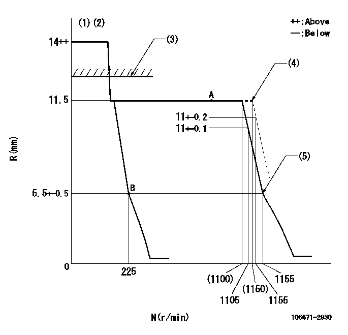
N:Pump speed
R:Rack position (mm)
(1)Target notch: K
(2)Tolerance for racks not indicated: +-0.05mm.
(3)RACK LIMIT
(4)At shipping
(5)Idle sub spring setting: L1.
----------
K=5 L1=5.5+-0.1mm
----------
----------
K=5 L1=5.5+-0.1mm
----------
Speed control lever angle
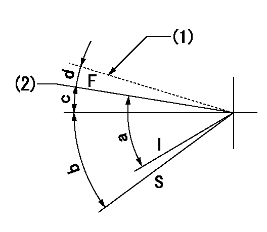
F:Full speed
I:Idle
S:Stop
(1)At shipping
(2)Pump speed = aa
----------
aa=1100r/min
----------
a=30deg+-5deg b=32deg+-3deg c=7deg+-5deg d=(2deg)
----------
aa=1100r/min
----------
a=30deg+-5deg b=32deg+-3deg c=7deg+-5deg d=(2deg)
Stop lever angle
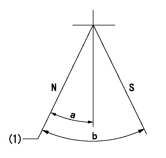
N:Pump normal
S:Stop the pump.
(1)Normal
----------
----------
a=19deg+-5deg b=53deg+-5deg
----------
----------
a=19deg+-5deg b=53deg+-5deg
Timing setting

(1)Pump vertical direction
(2)Coupling's key groove position at No 1 cylinder's beginning of injection
(3)-
(4)-
----------
----------
a=(7deg)
----------
----------
a=(7deg)
Information:
Clean/Replace Standard Air Cleaner Elements
Never service the air cleaner with the engine running since this will allow dirt to enter the engine. Check the vessel air duct inlet piping for leaks. Make all repairs to air ducts and inlet piping immediately, as dirt and debris could enter the engine causing damage to the turbocharger and engine components.Clean or replace elements using these recommendations and/or your weather and operating conditions, or when required by the restriction indicator.
1. Remove air cleaner cover and element. Clean or discard used element. Refer to SEBF8062, Guideline for Reusable Parts-Cleaning and Inspection of Air Filters.2. Cover air inlet opening with a clean cloth or towel to prevent dirt and debris from entering the engine.3. Clean the inside of the air cleaner cover and body.Cleaning with Water, Air or Detergent
Do not clean the filter elements by bumping or tapping them. Engine damage could result.
Filter elements can be cleaned with pressure air - 205 kPa (30 psi) maximum, pressure water - 280 kPa (40 psi) maximum, or detergent washing. Direct air or water along the pleats inside and outside of filter element. The element can be washed in warm water and nonsudsing household detergent. Rinse inside and outside the pleats and air dry fully.Inspect the filter elements after cleaning. Do not use a filter element with damaged pleats, gaskets or seals. Wrap and store the clean filter elements in a clean, dry place. Remove cloth from air inlet opening and install clean element while noting arrows indicating air flow on the side of the element. Install cover and reset service indicator.Cleaning Marine Air Cleaner Elements
1. Remove the air cleaner (1) and vacuum limiter element(s) (2). Tap the elements gently to dislodge any large particles. Gently brush the filter elements with a soft bristle brush.
NEVER use gasoline, steam, caustic or unapproved detergents or parts cleaning solvents. Never use high pressure water or air for cleaning. Using any of these liquids or methods will cause filter element damage.
Use the 102-9720 (U.S.) or 102-9721 (non-U.S.) Cleaning Kit exclusively. The kit contains detergent and oil products specifically for the maintenance of the air and vacuum limiter filter elements.2. Spray cleaning solution on the elements and allow to soak for ten minutes. Rinse the element(s) with low pressure water (tap water is acceptable) from the inside (clean side) out (dirty side) to remove dirt and debris and not drive them into element material.3. Shake off excess water and dry filter elements naturally and thoroughly. Inspect housing and clamp. Replace if necessary.
DO NOT dry elements with compressed air, open flame or heat dryers. Excess heat will shrink cotton fiber and compressed air may blow holes in material.
4. Inspect filter elements after cleaning for tears and/or holes in filter material. Do not re-use damaged filters, replace if necessary.
NEVER use automatic transmission fluid, motor oil, diesel fuel or lightweight oils to re-oil filter element. Do NOT install and operate engine with element dry.
5. Always re-oil filter elements before installing. Squeeze oil down into bottom
Have questions with 106671-2930?
Group cross 106671-2930 ZEXEL
Mitsubishi
Mitsubishi
106671-2930
9 400 616 765
ME059627
INJECTION-PUMP ASSEMBLY
6D22T
6D22T