Information injection-pump assembly
BOSCH
9 400 616 763
9400616763
ZEXEL
106671-2911
1066712911
MITSUBISHI
ME059629
me059629
Rating:
Service parts 106671-2911 INJECTION-PUMP ASSEMBLY:
1.
_
7.
COUPLING PLATE
8.
_
9.
_
11.
Nozzle and Holder
ME059621
12.
Open Pre:MPa(Kqf/cm2)
21.6{220}

15.
NOZZLE SET
Include in #1:
106671-2911
as INJECTION-PUMP ASSEMBLY
Cross reference number
BOSCH
9 400 616 763
9400616763
ZEXEL
106671-2911
1066712911
MITSUBISHI
ME059629
me059629
Zexel num
Bosch num
Firm num
Name
106671-2911
9 400 616 763
ME059629 MITSUBISHI
INJECTION-PUMP ASSEMBLY
6D22T K 14CA INJECTION PUMP ASSY PE6P,6PD PE
6D22T K 14CA INJECTION PUMP ASSY PE6P,6PD PE
Calibration Data:
Adjustment conditions
Test oil
1404 Test oil ISO4113 or {SAEJ967d}
1404 Test oil ISO4113 or {SAEJ967d}
Test oil temperature
degC
40
40
45
Nozzle and nozzle holder
105780-8140
Bosch type code
EF8511/9A
Nozzle
105780-0000
Bosch type code
DN12SD12T
Nozzle holder
105780-2080
Bosch type code
EF8511/9
Opening pressure
MPa
17.2
Opening pressure
kgf/cm2
175
Injection pipe
Outer diameter - inner diameter - length (mm) mm 8-3-600
Outer diameter - inner diameter - length (mm) mm 8-3-600
Overflow valve
131424-4620
Overflow valve opening pressure
kPa
255
221
289
Overflow valve opening pressure
kgf/cm2
2.6
2.25
2.95
Tester oil delivery pressure
kPa
157
157
157
Tester oil delivery pressure
kgf/cm2
1.6
1.6
1.6
Direction of rotation (viewed from drive side)
Right R
Right R
Injection timing adjustment
Direction of rotation (viewed from drive side)
Right R
Right R
Injection order
1-5-3-6-
2-4
Pre-stroke
mm
4.8
4.75
4.85
Beginning of injection position
Governor side NO.1
Governor side NO.1
Difference between angles 1
Cal 1-5 deg. 60 59.5 60.5
Cal 1-5 deg. 60 59.5 60.5
Difference between angles 2
Cal 1-3 deg. 120 119.5 120.5
Cal 1-3 deg. 120 119.5 120.5
Difference between angles 3
Cal 1-6 deg. 180 179.5 180.5
Cal 1-6 deg. 180 179.5 180.5
Difference between angles 4
Cyl.1-2 deg. 240 239.5 240.5
Cyl.1-2 deg. 240 239.5 240.5
Difference between angles 5
Cal 1-4 deg. 300 299.5 300.5
Cal 1-4 deg. 300 299.5 300.5
Injection quantity adjustment
Adjusting point
A
Rack position
9.7
Pump speed
r/min
1100
1100
1100
Average injection quantity
mm3/st.
128.5
125.5
131.5
Max. variation between cylinders
%
0
-3
3
Basic
*
Fixing the lever
*
Injection quantity adjustment_02
Adjusting point
C
Rack position
5.9+-0.5
Pump speed
r/min
375
375
375
Average injection quantity
mm3/st.
14
11.5
16.5
Max. variation between cylinders
%
0
-15
15
Fixing the rack
*
Injection quantity adjustment_03
Adjusting point
D
Rack position
-
Pump speed
r/min
100
100
100
Average injection quantity
mm3/st.
130
110
150
Fixing the lever
*
Remarks
After startup boost setting
After startup boost setting
Timer adjustment
Pump speed
r/min
650--
Advance angle
deg.
0
0
0
Remarks
Start
Start
Timer adjustment_02
Pump speed
r/min
600
Advance angle
deg.
0.5
Timer adjustment_03
Pump speed
r/min
900
Advance angle
deg.
1.6
1.1
2.1
Timer adjustment_04
Pump speed
r/min
1000
Advance angle
deg.
2.2
1.7
2.7
Timer adjustment_05
Pump speed
r/min
-
Advance angle
deg.
3
2.5
3.5
Remarks
Measure the actual speed, stop
Measure the actual speed, stop
Test data Ex:
Governor adjustment

N:Pump speed
R:Rack position (mm)
(1)Lever ratio: RT
(2)Target shim dimension: TH
(3)Tolerance for racks not indicated: +-0.05mm.
(4)Excess fuel setting for starting: SXL (N = N1)
(5)Main spring setting
(6)Damper spring setting
----------
RT=1 TH=2.6mm SXL=10.2+-0.1mm N1=470r/min
----------
----------
RT=1 TH=2.6mm SXL=10.2+-0.1mm N1=470r/min
----------
Speed control lever angle
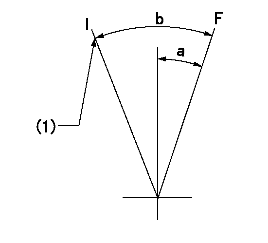
F:Full speed
I:Idle
(1)Stopper bolt setting
----------
----------
a=(7deg)+-5deg b=(14deg)+-5deg
----------
----------
a=(7deg)+-5deg b=(14deg)+-5deg
0000000901
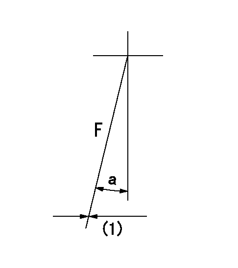
F:Full load
(1)Fix using the stopper bolt.
----------
----------
a=7.5deg+-5deg
----------
----------
a=7.5deg+-5deg
Stop lever angle

N:Pump normal
S:Stop the pump.
(1)Drive side
----------
----------
a=25deg+-5deg b=64deg+-5deg
----------
----------
a=25deg+-5deg b=64deg+-5deg
Timing setting

(1)Pump vertical direction
(2)Coupling's key groove position at No 1 cylinder's beginning of injection
(3)-
(4)-
----------
----------
a=(7deg)
----------
----------
a=(7deg)
Information:
Adjust - to conform and correspond to specifications. Check - to observe for satisfactory conditions, accuracy, safety or performance. Exchange - to trade a worn or failing component for a remanufactured or rebuilt component. Inspect - to examine closely, in critical appraisal, while testing or evaluating components or systems. Inspect/Rebuild or Exchange - to examine closely; then making the decision on repair option (Rebuild or Exchange). Lubricate - to apply a lubricant (oil, grease, etc.) as specified for reducing friction, heat and wear between solid surfaces. Protective Devices - indicators such as gauges, lights, emergency shutoffs, etc., that alert the pilot that a potential problem may exist. Failure to respond to these indicators in a timely manner could result in serious engine damage. Rebuild - to repair a worn or failing component with new parts, components and/or remanufactured components. Replace - to install something new, remanufactured or rebuilt in place of an existing worn or failing component. Service Hours (Electrical) - records the time (clock hours) the engine is actually running but does not reflect variations in speed, load, etc. The Maintenance Schedules are developed for calendar time, clock hours or fuel consumption. For most users, Service Meter Units and clock hours can be roughly equal. However, Caterpillar recommends that fuel consumption be used as the preferred method of establishing intervals rather than time, SMU's or clock hours.Maintenance Intervals
The Maintenance Schedule requires all previous interval maintenance items to be performed first. For instance, if the Every 250 Hour maintenance is being done, then the Every 50 Hour and Daily maintenance items must be completed BEFORE performing the Every 250 Hour maintenance.Engines may be equipped with various optional components and the charts may recommend maintenance for items not installed on your engine. Simply disregard reference to any extraneous items. If unsure of any item, consult your Caterpillar dealer.Overhaul Interval
The last interval in the chart lists the components inspected, rebuilt, exchanged or replaced at overhaul. OVERHAUL is defined as the interval at which the major wear items in the engine should be replaced. The Overhaul interval represents overhaul of a non-failed engine. In other words, the engine is being rebuilt with certain new parts replacing worn parts such as piston rings, engine rod and main bearings, valves and valve seats., etc.Incidental to the replacement of these relatively few parts is the complete inspection of all other parts that are visible during the overhaul of the engine. The disassembly required to do an overhaul means that disturbed seals and gaskets, etc., will be replaced, and the internal passages of the engine and block be cleaned.* The OVERHAUL interval assumes that regular maintenance recommendations in the rest of the chart have been carefully followed.* Some users may obtain significantly longer or shorter life than the chart recommends between overhauls, but if the recommended intervals are followed, OVERHAULS will occur BEFORE actual FAILURE, and the total COST of operation will be minimized.Although most users will obtain more life between overhauls than
Have questions with 106671-2911?
Group cross 106671-2911 ZEXEL
Mitsubishi
Mitsubishi
106671-2911
9 400 616 763
ME059629
INJECTION-PUMP ASSEMBLY
6D22T
6D22T