Information injection-pump assembly
ZEXEL
106671-2880
1066712880

Rating:
Cross reference number
ZEXEL
106671-2880
1066712880
Zexel num
Bosch num
Firm num
Name
Calibration Data:
Adjustment conditions
Test oil
1404 Test oil ISO4113 or {SAEJ967d}
1404 Test oil ISO4113 or {SAEJ967d}
Test oil temperature
degC
40
40
45
Nozzle and nozzle holder
105780-8140
Bosch type code
EF8511/9A
Nozzle
105780-0000
Bosch type code
DN12SD12T
Nozzle holder
105780-2080
Bosch type code
EF8511/9
Opening pressure
MPa
17.2
Opening pressure
kgf/cm2
175
Injection pipe
Outer diameter - inner diameter - length (mm) mm 8-3-600
Outer diameter - inner diameter - length (mm) mm 8-3-600
Overflow valve
131424-4620
Overflow valve opening pressure
kPa
255
221
289
Overflow valve opening pressure
kgf/cm2
2.6
2.25
2.95
Tester oil delivery pressure
kPa
157
157
157
Tester oil delivery pressure
kgf/cm2
1.6
1.6
1.6
Direction of rotation (viewed from drive side)
Right R
Right R
Injection timing adjustment
Direction of rotation (viewed from drive side)
Right R
Right R
Injection order
1-5-3-6-
2-4
Pre-stroke
mm
4.8
4.75
4.85
Beginning of injection position
Governor side NO.1
Governor side NO.1
Difference between angles 1
Cal 1-5 deg. 60 59.5 60.5
Cal 1-5 deg. 60 59.5 60.5
Difference between angles 2
Cal 1-3 deg. 120 119.5 120.5
Cal 1-3 deg. 120 119.5 120.5
Difference between angles 3
Cal 1-6 deg. 180 179.5 180.5
Cal 1-6 deg. 180 179.5 180.5
Difference between angles 4
Cyl.1-2 deg. 240 239.5 240.5
Cyl.1-2 deg. 240 239.5 240.5
Difference between angles 5
Cal 1-4 deg. 300 299.5 300.5
Cal 1-4 deg. 300 299.5 300.5
Injection quantity adjustment
Adjusting point
A
Rack position
10.1
Pump speed
r/min
1050
1050
1050
Average injection quantity
mm3/st.
130
127
133
Max. variation between cylinders
%
0
-3
3
Basic
*
Fixing the lever
*
Injection quantity adjustment_02
Adjusting point
B
Rack position
5.3+-0.5
Pump speed
r/min
225
225
225
Average injection quantity
mm3/st.
15
12.4
17.6
Max. variation between cylinders
%
0
-15
15
Fixing the rack
*
Injection quantity adjustment_03
Adjusting point
C
Rack position
12.3+-0.
5
Pump speed
r/min
100
100
100
Average injection quantity
mm3/st.
133
113
153
Fixing the lever
*
Rack limit
*
Timer adjustment
Pump speed
r/min
650--
Advance angle
deg.
0
0
0
Remarks
Start
Start
Timer adjustment_02
Pump speed
r/min
600
Advance angle
deg.
0.5
Timer adjustment_03
Pump speed
r/min
900
Advance angle
deg.
1.6
1.1
2.1
Timer adjustment_04
Pump speed
r/min
1100
Advance angle
deg.
3
2.5
3.5
Remarks
Finish
Finish
Test data Ex:
Governor adjustment

N:Pump speed
R:Rack position (mm)
(1)Target notch: K
(2)RACK LIMIT
(3)Torque spring does not operate.
(4)At shipping
(5)Rack difference between N = N1 and N = N2
(6)Rack difference between N = N3 and N = N4
----------
K=9 N1=1050r/min N2=700r/min N3=1050r/min N4=450r/min
----------
----------
K=9 N1=1050r/min N2=700r/min N3=1050r/min N4=450r/min
----------
Speed control lever angle
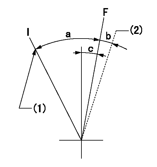
F:Full speed
I:Idle
(1)Stopper bolt setting
(2)At shipping
----------
----------
a=31deg+-5deg b=(2deg) c=7deg+-5deg
----------
----------
a=31deg+-5deg b=(2deg) c=7deg+-5deg
Stop lever angle

N:Pump normal
S:Stop the pump.
----------
----------
a=19deg+-5deg b=53deg+-5deg
----------
----------
a=19deg+-5deg b=53deg+-5deg
Timing setting

(1)Pump vertical direction
(2)Coupling's key groove position at No 1 cylinder's beginning of injection
(3)-
(4)-
----------
----------
a=(7deg)
----------
----------
a=(7deg)
Information:
Improper jumper cable connections can cause an explosion resulting in personal injury. Do not allow jump cable ends to contact each other or the engine.Prevent sparks near the batteries. They could cause vapors to explode. Do not smoke when observing battery electrolyte levels.Electrolyte is an acid and can cause personal injury if it contacts skin or eyes. Always wear eye protection when starting an engine with jump cables.
Use only equal voltage for jump starting. The use of a welder or higher voltage will damage the electrical system. Jump only using a battery source with the same voltage as the stalled engine.
Turn off all lights and accessories on the stalled vessel. Otherwise, they will operate when the jump source is connected. Before attaching the jumper cables, move START switch to the OFF position.Always connect the battery positive (+) to battery positive (+) and the battery negative (-) to battery negative (-). When using jumper cables, be sure to connect in parallel: POSITIVE (+) cable to POSITIVE (+) terminal of battery which is connected to starting motor solenoid and NEGATIVE (-) cable from external source to starting motor NEGATIVE (-) terminal. If not equipped with a starting motor NEGATIVE terminal, connect to the engine block.Do not allow the free ends of jumper cables to touch the engine. This helps avoid sparks. Do not reverse the battery cables. The alternator can be damaged. Attach ground cable last and remove first. Many batteries thought to be unusable, are still rechargeable. Refer to Special Instruction, SEHS7633, Battery Test Procedure, available from your Caterpillar dealer, for complete testing and charging information.When boost starting, refer to the instructions that follow to properly start the engine.1. Connect one end of cable to the POSITIVE (+) (ungrounded) terminal of the battery on the engine being started. Connect the other end to the POSITIVE (+) terminal of the power source.2. Connect one end of the second cable to the NEGATIVE (-) terminal of the power source. Connect the other end to the starting motor ground NEGATIVE (-) terminal or to the engine block. This prevents potential sparks from igniting combustible gases produced by some batteries.3. Begin cranking engine to start the engine and achieve idle speed after making sure the marine transmission is in NEUTRAL. Start the engine using the starting procedure described previously.4. After the engine starts, disconnect the cable from the starting motor ground NEGATIVE (-) terminal or engine block first. Disconnect the other end from the NEGATIVE (-) terminal of the power source. Disconnect the cable from the POSITIVE (+) terminal of the battery on the engine being started. Disconnect the other end of cable from the POSITIVE (+) terminal of the power source.To prevent electrical discharge damage, check to make sure the engine's electrical system has an engine-to-battery ground connection. For engines which have the alternator connected to an engine component, a ground strap must connect that component to the battery.If the engine is not electrically connected directly to the rails through mounting bolts,