Information injection-pump assembly
BOSCH
9 400 616 756
9400616756
ZEXEL
106671-2641
1066712641
MITSUBISHI
ME056309
me056309

Rating:
Cross reference number
BOSCH
9 400 616 756
9400616756
ZEXEL
106671-2641
1066712641
MITSUBISHI
ME056309
me056309
Zexel num
Bosch num
Firm num
Name
Calibration Data:
Adjustment conditions
Test oil
1404 Test oil ISO4113 or {SAEJ967d}
1404 Test oil ISO4113 or {SAEJ967d}
Test oil temperature
degC
40
40
45
Nozzle and nozzle holder
105780-8140
Bosch type code
EF8511/9A
Nozzle
105780-0000
Bosch type code
DN12SD12T
Nozzle holder
105780-2080
Bosch type code
EF8511/9
Opening pressure
MPa
17.2
Opening pressure
kgf/cm2
175
Injection pipe
Outer diameter - inner diameter - length (mm) mm 8-3-600
Outer diameter - inner diameter - length (mm) mm 8-3-600
Overflow valve opening pressure
kPa
255
221
289
Overflow valve opening pressure
kgf/cm2
2.6
2.25
2.95
Tester oil delivery pressure
kPa
157
157
157
Tester oil delivery pressure
kgf/cm2
1.6
1.6
1.6
Direction of rotation (viewed from drive side)
Right R
Right R
Injection timing adjustment
Direction of rotation (viewed from drive side)
Right R
Right R
Injection order
1-5-3-6-
2-4
Pre-stroke
mm
4.8
4.75
4.85
Beginning of injection position
Governor side NO.1
Governor side NO.1
Difference between angles 1
Cal 1-5 deg. 60 59.5 60.5
Cal 1-5 deg. 60 59.5 60.5
Difference between angles 2
Cal 1-3 deg. 120 119.5 120.5
Cal 1-3 deg. 120 119.5 120.5
Difference between angles 3
Cal 1-6 deg. 180 179.5 180.5
Cal 1-6 deg. 180 179.5 180.5
Difference between angles 4
Cyl.1-2 deg. 240 239.5 240.5
Cyl.1-2 deg. 240 239.5 240.5
Difference between angles 5
Cal 1-4 deg. 300 299.5 300.5
Cal 1-4 deg. 300 299.5 300.5
Injection quantity adjustment
Adjusting point
-
Rack position
8.1
Pump speed
r/min
700
700
700
Each cylinder's injection qty
mm3/st.
109
106.3
111.7
Basic
*
Fixing the rack
*
Standard for adjustment of the maximum variation between cylinders
*
Injection quantity adjustment_02
Adjusting point
F
Rack position
5+-0.5
Pump speed
r/min
500
500
500
Each cylinder's injection qty
mm3/st.
16.5
14
19
Fixing the rack
*
Standard for adjustment of the maximum variation between cylinders
*
Injection quantity adjustment_03
Adjusting point
A
Rack position
R1(8.1)
Pump speed
r/min
700
700
700
Average injection quantity
mm3/st.
109
108
110
Fixing the lever
*
Injection quantity adjustment_04
Adjusting point
B
Rack position
R1(8.1)
Pump speed
r/min
1100
1100
1100
Average injection quantity
mm3/st.
123
119
127
Difference in delivery
mm3/st.
8
8
8
Fixing the lever
*
Injection quantity adjustment_05
Adjusting point
C
Rack position
5.7+-0.5
Pump speed
r/min
225
225
225
Each cylinder's injection qty
mm3/st.
16.5
14
19
Fixing the rack
*
Remarks
(check)
(check)
Injection quantity adjustment_06
Adjusting point
E
Rack position
10.5++
Pump speed
r/min
100
100
100
Average injection quantity
mm3/st.
125
105
145
Fixing the lever
*
Timer adjustment
Pump speed
r/min
950
Advance angle
deg.
0.5
Timer adjustment_02
Pump speed
r/min
1050
Advance angle
deg.
2.2
1.7
2.7
Timer adjustment_03
Pump speed
r/min
1150
Advance angle
deg.
5.5
5
6
Remarks
Finish
Finish
Test data Ex:
Governor adjustment
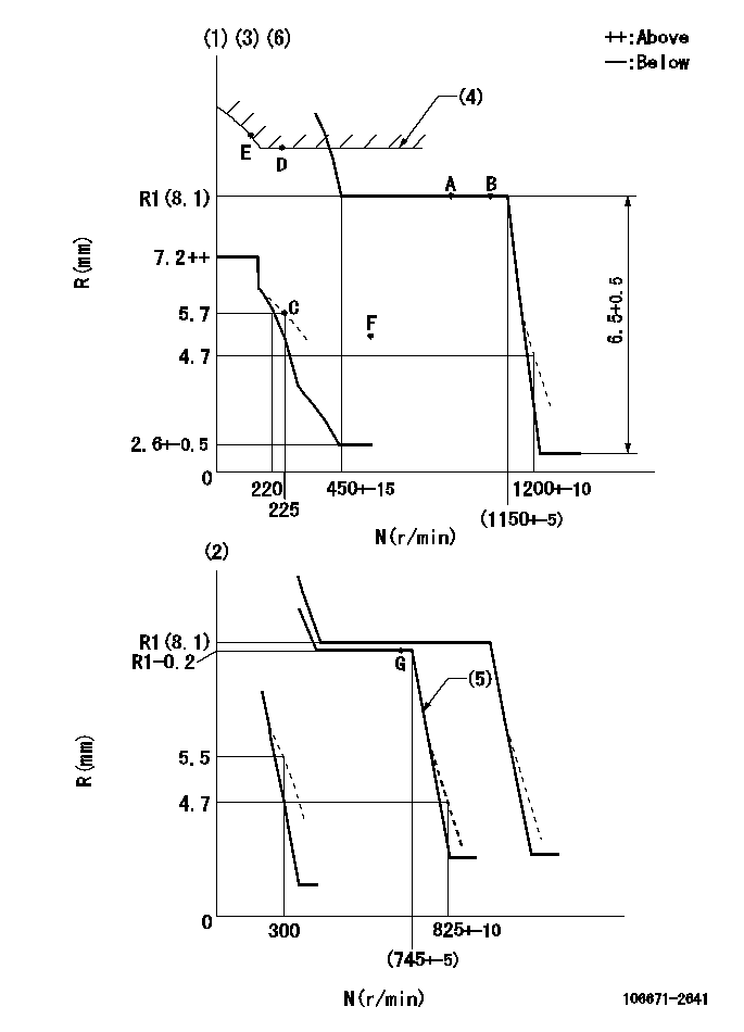
N:Pump speed
R:Rack position (mm)
(1)Adjust with speed control lever at full position (minimum-maximum speed specification)
(2)Adjust with the load control lever in the full position (variable speed specification).
(3)Target shim dimension: TH
(4)Excess fuel setting for starting: SXL
(5)When air cylinder is operating.
(6)Beginning of damper spring operation: DL
----------
TH=2.4mm SXL=10.5+-0.1mm DL=6-0.2mm
----------
----------
TH=2.4mm SXL=10.5+-0.1mm DL=6-0.2mm
----------
Speed control lever angle
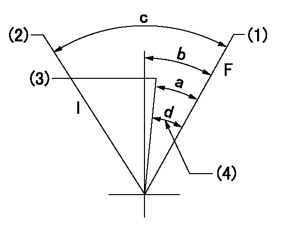
F:Full speed
I:Idle
(1)When pump speed set at aa
(2)When pump speed set at bb
(3)Pump speed cc
(4)Possible adjusting range
----------
aa=1150r/min bb=300r/min cc=750r/min
----------
a=10deg+-5deg b=10deg+-5deg c=22deg+-5deg d=10deg
----------
aa=1150r/min bb=300r/min cc=750r/min
----------
a=10deg+-5deg b=10deg+-5deg c=22deg+-5deg d=10deg
0000000901
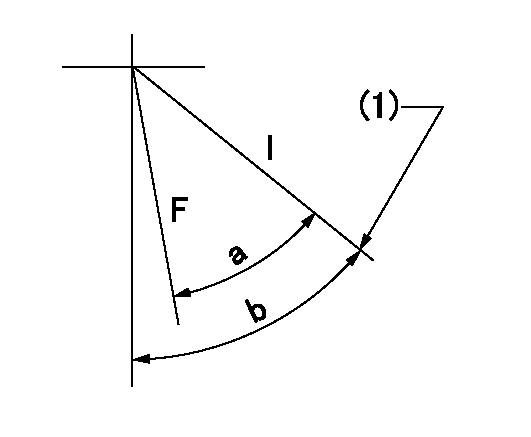
F:Full load
I:Idle
(1)Stopper bolt setting
----------
----------
a=20deg+-3deg b=21deg+-5deg
----------
----------
a=20deg+-3deg b=21deg+-5deg
Stop lever angle

N:Pump normal
S:Stop the pump.
(1)Stopper bolt setting
(2)Rack position = aa
(3)Rack position bb
(4)Free (at shipping)
----------
aa=4.1-0.5mm bb=13.1mm
----------
a=27deg+-5deg b=(56deg)+-5deg c=0deg+7deg-5deg
----------
aa=4.1-0.5mm bb=13.1mm
----------
a=27deg+-5deg b=(56deg)+-5deg c=0deg+7deg-5deg
0000001501 MICRO SWITCH
Adjustment of the micro-switch
Adjust the bolt to obtain the following lever position when the micro-switch is ON.
(1)Speed N1
(2)Rack position Ra
----------
N1=325+-5r/min Ra=5.4mm
----------
----------
N1=325+-5r/min Ra=5.4mm
----------
0000001601 2-STAGE CHANGEOVER DEVICE

RFD governor 2 stage changeover mechanism adjustment outline
(A) Bolt
(B) bolt
(c) Nut
(D) Return spring
(E) Bolt
(F) Bolt
(G) Screw
(H) Bolt
(I) Load lever
(J) Speed lever
(K) Air cylinder
(M Air inlet
Figure 1 is only for reference. Lever shape, etc, may vary.
1. Minimum-maximum speed specification adjustment (when running)
(a) Without applying air to the air cylinder, loosen bolts (A) and (B).
(1)High speed return L setting
(a) In the speed range Nf~Nf - 300r/min, adjust using the speed adjusting bolt to determine the temporary beginning of high speed control speed.
(b) Determine the rack position in the vicinity of Rf using the full load lever.
(c) Increase speed and confirm return distance L.
(d) Adjust using the tension lever bolt to obtain L.
(2)Setting full load rack position Rf
(a) Move the load control lever to the full side.
(b) Adjust the full load adjusting bolt so that Rf can be obtained, then fix.
(3)Setting the beginning of high speed operation Nf
(a) Adjust using bolt (E) so that Nf can be obtained, and then fix.
(4)Idle control setting (Re, Ni, Rc)
(a) Set the speed at Ns + 200r/min and move the load control lever to the idle side.
(b) Fix the lever in the position where Re can be obtained.
(c) Next, decrease speed to Ni and screw in the idle spring.
(d) Adjust to obtain rack position Ri.
(e) Increase the speed and after confirming that the rack position is Re at Ns, set the speed at 0.
(f) Confirm protrusion position Rc at idle.
(5)Damper spring adjustment
(a) Increase speed and set the speed at the rack position Rd - 0.1 mm
(b) Set using the damper spring so that the rack position Rd can be obtained.
(c) When Rd is not specified, Rd = Ri - 0.5 mm.
(6)High speed droop confirmation
(a) Return the load control lever to the full load lever position.
(b) Increase the speed and confirm that Rf can be obtained at Nf r/min.
(c) Confirm that speed is Nh at rack position Rh.
2. Variable speed specification adjustment (at operation)
(a) Remove return spring (D).
(b) Apply air pressure of 245~294 kPa {2.5~3 kg/cm2} to the air cylinder.
(c) Perform the following adjustment in this condition.
(1)Setting full load rack position Rf'
(a) Pull the load lever to the idle side.
(b) Obtain rack position Rf' using the nut (C). (Pump speed is Nf'-50 r/min.)
(2)Setting full speed Nf'
(a) Adjust using bolt (B) so that Nf can be obtained, and then fix.
(3)Low speed side setting
(a) At 350r/min, set bolt (F) at beginning of governor operation position, then fix.
3. Bolt (A) adjustment
(1)Install return spring (D) and perform the adjustments below at air pressure 0.
(a) Set at speed Nf using bolt (E).
(b) Screw in bolt (A).
(c) Screw in 1 more turn from the speed lever contact position
(d) Fix bolt (A).
(e) At this time confirm that the air cylinder's shaft moves approximately 1 mm towards the governor.
4. Lever operation confirmation using the air cylinder
(1)Apply 588 kPa {6 kg/cm2} air pressure to the air cylinder.
(2)Confirm that the cylinder piston is moved 50 mm by the spring (D).
----------
----------
----------
----------
Information:
Safety is everyone's business and is basically the use of good common sense. A general guide of safety precautions are given below, but each installation has its own peculiarities which cannot always be predicted and covered by established rules. Past experience and common sense are needed for the necessary safety measures. Attention to safety will help avoid serious accidents. Be alert. Watch for hazards. Use preventive measures. Correct deficiencies immediately.The following safety precautions are a general guide to safe operation:1. To prevent personal injury, install guards over all exposed rotating parts.2. To prevent hearing damage, wear ear protective devices if working inside an enclosed engine room with engine running.3. To prevent head injury, wear safety hat when working in the area of overhead equipment.4. Wear safety glasses and shoes as required. 5. Do not wear loose clothing whenever working around engines or machinery.6. Wipe up spilled oil, fuel or coolant.7. Keep batteries in a well ventilated area. Do not smoke around batteries. Hydrogen gas, which is present in the area of the batteries, is highly explosive.8. Provide adequate and safe waste oil disposal.9. Store oily rags in fireproof containers. Don't leave rags on engine.
When using pressure air, wear safety glasses and protective clothing. Maximum air pressure, used for cleaning, must be below 30 PSI (2 kg/cm2).
10. Remove all tools, electrical cords and other loose items from the engine before starting.11. Disconnect and tape the battery ground lead before working on an engine to prevent accidental starting. Be sure an automatic start-stop system cannot operate and start the engine while working on it.12. Do not attempt repairs you do not understand. Follow instructions.13. Stop engine before adjusting or repairing engine or driven equipment.14. Remove radiator cap slowly. Cooling systems can be pressurized and hot fluid will flash to steam as pressure is removed.15. Never start an engine with the governor linkage disconnected.16. Replace or repair broken or damaged equipment. Use proper tools.17. Do not smoke while refueling. Observe NO SMOKING signs.18. Never store flammable liquids near the engine.19. All electrical equipment must be grounded according to local building codes.20. Check all connections periodically for tightness and insulation.21. Insulate all connections and disconnected wires.22. Do not use carbon tetrachloride fire extinguishers. Fumes are toxic and the liquid has a deteriorating effect on insulation. 23. Do not touch the heat sink on the generator regulator when the generator is running. It is electrically "hot".24. Do not work on electrically "hot" equipment.25. Always disconnect the engine starter circuit when working on the generator.26. Hot engine oil can cause burns when drained. Allow the oil to cool below 140°F or provide protection when draining the hot oil.27. Never remove a plug to check pressure with the engine running. Shut down the engine and assure there is no pressure before removing plug.28. When starting an engine after repair, make provisions for shutting off air supply in case there is an overspeed on start up.29. Never look into an open cylinder port and turn over