Information injection-pump assembly
ZEXEL
106671-2610
1066712610

Rating:
Cross reference number
ZEXEL
106671-2610
1066712610
Zexel num
Bosch num
Firm num
Name
Calibration Data:
Adjustment conditions
Test oil
1404 Test oil ISO4113 or {SAEJ967d}
1404 Test oil ISO4113 or {SAEJ967d}
Test oil temperature
degC
40
40
45
Nozzle and nozzle holder
105780-8140
Bosch type code
EF8511/9A
Nozzle
105780-0000
Bosch type code
DN12SD12T
Nozzle holder
105780-2080
Bosch type code
EF8511/9
Opening pressure
MPa
17.2
Opening pressure
kgf/cm2
175
Injection pipe
Outer diameter - inner diameter - length (mm) mm 8-3-600
Outer diameter - inner diameter - length (mm) mm 8-3-600
Overflow valve opening pressure
kPa
255
221
289
Overflow valve opening pressure
kgf/cm2
2.6
2.25
2.95
Tester oil delivery pressure
kPa
157
157
157
Tester oil delivery pressure
kgf/cm2
1.6
1.6
1.6
Direction of rotation (viewed from drive side)
Right R
Right R
Injection timing adjustment
Direction of rotation (viewed from drive side)
Right R
Right R
Injection order
1-5-3-6-
2-4
Pre-stroke
mm
4.8
4.75
4.85
Beginning of injection position
Governor side NO.1
Governor side NO.1
Difference between angles 1
Cal 1-5 deg. 60 59.5 60.5
Cal 1-5 deg. 60 59.5 60.5
Difference between angles 2
Cal 1-3 deg. 120 119.5 120.5
Cal 1-3 deg. 120 119.5 120.5
Difference between angles 3
Cal 1-6 deg. 180 179.5 180.5
Cal 1-6 deg. 180 179.5 180.5
Difference between angles 4
Cyl.1-2 deg. 240 239.5 240.5
Cyl.1-2 deg. 240 239.5 240.5
Difference between angles 5
Cal 1-4 deg. 300 299.5 300.5
Cal 1-4 deg. 300 299.5 300.5
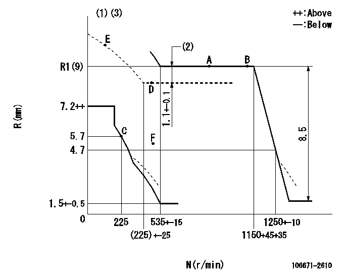
Injection quantity adjustment
Adjusting point
-
Rack position
9
Pump speed
r/min
600
600
600
Each cylinder's injection qty
mm3/st.
136
133
139
Basic
*
Fixing the rack
*
Standard for adjustment of the maximum variation between cylinders
*
Injection quantity adjustment_02
Adjusting point
F
Rack position
5+-0.5
Pump speed
r/min
500
500
500
Each cylinder's injection qty
mm3/st.
16.5
14
19
Fixing the rack
*
Standard for adjustment of the maximum variation between cylinders
*
Injection quantity adjustment_03
Adjusting point
A
Rack position
R1(9)
Pump speed
r/min
600
600
600
Average injection quantity
mm3/st.
136
135
137
Fixing the lever
*
Boost pressure
kPa
60
60
Boost pressure
mmHg
460
460
Injection quantity adjustment_04
Adjusting point
B
Rack position
R1(9)
Pump speed
r/min
1100
1100
1100
Average injection quantity
mm3/st.
148
144.8
151.2
Difference in delivery
mm3/st.
6.4
6.4
6.4
Fixing the lever
*
Boost pressure
kPa
60
60
Boost pressure
mmHg
460
460
Injection quantity adjustment_05
Adjusting point
D
Rack position
7.9+-0.5
Pump speed
r/min
500
500
500
Average injection quantity
mm3/st.
107.5
104.3
110.7
Fixing the lever
*
Boost pressure
kPa
0
0
0
Boost pressure
mmHg
0
0
0
Injection quantity adjustment_06
Adjusting point
C
Rack position
5.7+-0.5
Pump speed
r/min
225
225
225
Each cylinder's injection qty
mm3/st.
16.5
14
19
Fixing the rack
*
Boost pressure
kPa
0
0
0
Boost pressure
mmHg
0
0
0
Remarks
(check)
(check)
Injection quantity adjustment_07
Adjusting point
E
Rack position
-
Pump speed
r/min
100
100
100
Average injection quantity
mm3/st.
105
65
145
Fixing the lever
*
Boost pressure
kPa
0
0
0
Boost pressure
mmHg
0
0
0
Boost compensator adjustment
Pump speed
r/min
600
600
600
Rack position
7.9
Boost pressure
kPa
28
28
28
Boost pressure
mmHg
210
210
210
Boost compensator adjustment_02
Pump speed
r/min
600
600
600
Rack position
8.65
Boost pressure
kPa
37.3
36
38.6
Boost pressure
mmHg
280
270
290
Boost compensator adjustment_03
Pump speed
r/min
600
600
600
Rack position
R1(9)
Boost pressure
kPa
48
41.3
54.7
Boost pressure
mmHg
360
310
410
Timer adjustment
Pump speed
r/min
950--
Advance angle
deg.
0
0
0
Remarks
Start
Start
Timer adjustment_02
Pump speed
r/min
900
Advance angle
deg.
0.5
Timer adjustment_03
Pump speed
r/min
1000
Advance angle
deg.
2.5
2
3
Remarks
Finish
Finish
Test data Ex:
Governor adjustment
N:Pump speed
R:Rack position (mm)
(1)Beginning of damper spring operation: DL
(2)Boost compensator stroke
(3)Boost compensator cancel stroke: BSL
----------
DL=4.5-0.2mm BSL=2.2mm
----------
----------
DL=4.5-0.2mm BSL=2.2mm
----------
Speed control lever angle

F:Full speed
----------
----------
a=18deg+-5deg
----------
----------
a=18deg+-5deg
0000000901
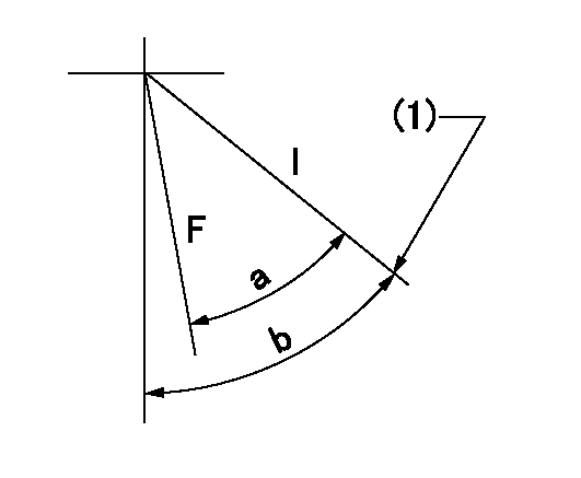
F:Full load
I:Idle
(1)Stopper bolt setting
----------
----------
a=28deg+-3deg b=29.5deg+-5deg
----------
----------
a=28deg+-3deg b=29.5deg+-5deg
Stop lever angle

N:Pump normal
S:Stop the pump.
(1)Rack position = aa
(2)Stopper bolt setting
(3)Rack position bb
(4)Free (at delivery)
----------
aa=4.1-0.5mm bb=13.3mm
----------
a=26deg+-5deg b=(38deg) c=0deg+7deg+5deg
----------
aa=4.1-0.5mm bb=13.3mm
----------
a=26deg+-5deg b=(38deg) c=0deg+7deg+5deg
0000001501 MICRO SWITCH
Adjustment of the micro-switch
Adjust the bolt to obtain the following lever position when the micro-switch is ON.
(1)Speed N1
(2)Rack position Ra
----------
N1=325+-5r/min Ra=5.4mm
----------
----------
N1=325+-5r/min Ra=5.4mm
----------
Information:
1. Remove suction bell (3) and tubes, oil supply tube (2) and Brake Saver oil supply tube (1) from the engine block and oil pump. 2. Remove three bolts (5) and oil pump (4) from the engine. The following steps are for installation of the oil pump.3. Put oil pump (4) in position on the engine. Make sure the oil pump gear is engaged with the crankshaft gear, and install three bolts (5) that hold the oil pump.4. Put clean engine oil on the O-ring seals on the oil tubes.5. Install suction bell (3) and tubes, oil supply tube (2) and the BrakeSaver oil supply tube (1).End By:a. install oil pan (BrakeSaver)Disassemble Oil Pump (BrakeSaver)
Start By:a. remove oil pump (Brake Saver) 1. Remove the bolt and washer that hold drive gear (1) on the shaft.2. Use tooling (A) to remove drive gear (1) from the shaft. Remove the key from the shaft. Put alignment marks on the pump bodies so they can be assembled in the correct position. 3. Remove retainer (3) for the bypass valve. Remove the spring and bypass valve.4. Remove bolts (4) that hold pump body (2) to the main pump body. Remove pump body (2).5. Use tooling (B) to remove the bearings from pump body (2). 6. Remove gears (7). Put identification marks on the gears so they can be assembled in the same position.7. Remove spacer (6) from main oil pump body (5). Use tooling (B) to remove the bearings from spacer (6).8. Remove the gears from main oil pump body (5). 9. Use tooling (B) to remove the bearings from the main oil pump body.Assemble Oil Pump (BrakeSaver)
1. Use tooling (B) to install bearings (8) until they are even with the outside surface of main oil pump body (5). Install bearings (8) so the joints in the bearings are 30 ° 15 ° from the center line