Information injection-pump assembly
BOSCH
9 400 619 766
9400619766
ZEXEL
106671-2594
1066712594
MITSUBISHI-HEAV
3626510140
3626510140
Rating:
Service parts 106671-2594 INJECTION-PUMP ASSEMBLY:
1.
_
7.
COUPLING PLATE
8.
_
9.
_
11.
Nozzle and Holder
12.
Open Pre:MPa(Kqf/cm2)
21.6{220}
15.
NOZZLE SET
Include in #1:
106671-2594
as INJECTION-PUMP ASSEMBLY
Cross reference number
BOSCH
9 400 619 766
9400619766
ZEXEL
106671-2594
1066712594
MITSUBISHI-HEAV
3626510140
3626510140
Zexel num
Bosch num
Firm num
Name
Calibration Data:
Adjustment conditions
Test oil
1404 Test oil ISO4113 or {SAEJ967d}
1404 Test oil ISO4113 or {SAEJ967d}
Test oil temperature
degC
40
40
45
Nozzle and nozzle holder
105780-8130
Bosch type code
EFEP215A
Nozzle
105780-0050
Bosch type code
DN6TD119NP1T
Nozzle holder
105780-2090
Bosch type code
EFEP215
Opening pressure
MPa
17.2
Opening pressure
kgf/cm2
175
Injection pipe
Outer diameter - inner diameter - length (mm) mm 8-3-600
Outer diameter - inner diameter - length (mm) mm 8-3-600
Overflow valve
133424-0221
Overflow valve opening pressure
kPa
157
123
191
Overflow valve opening pressure
kgf/cm2
1.6
1.25
1.95
Tester oil delivery pressure
kPa
157
157
157
Tester oil delivery pressure
kgf/cm2
1.6
1.6
1.6
Direction of rotation (viewed from drive side)
Right R
Right R
Injection timing adjustment
Direction of rotation (viewed from drive side)
Right R
Right R
Injection order
1-5-3-6-
2-4
Pre-stroke
mm
3.7
3.65
3.75
Beginning of injection position
Governor side NO.1
Governor side NO.1
Difference between angles 1
Cal 1-5 deg. 60 59.5 60.5
Cal 1-5 deg. 60 59.5 60.5
Difference between angles 2
Cal 1-3 deg. 120 119.5 120.5
Cal 1-3 deg. 120 119.5 120.5
Difference between angles 3
Cal 1-6 deg. 180 179.5 180.5
Cal 1-6 deg. 180 179.5 180.5
Difference between angles 4
Cyl.1-2 deg. 240 239.5 240.5
Cyl.1-2 deg. 240 239.5 240.5
Difference between angles 5
Cal 1-4 deg. 300 299.5 300.5
Cal 1-4 deg. 300 299.5 300.5
Injection quantity adjustment
Adjusting point
A
Rack position
12.5
Pump speed
r/min
1150
1150
1150
Average injection quantity
mm3/st.
282
275
289
Max. variation between cylinders
%
0
-3
3
Basic
*
Fixing the lever
*
Injection quantity adjustment_02
Adjusting point
B
Rack position
7.1+-0.5
Pump speed
r/min
250
250
250
Average injection quantity
mm3/st.
30
27
33
Max. variation between cylinders
%
0
-10
10
Fixing the rack
*
Injection quantity adjustment_03
Adjusting point
C
Rack position
-
Pump speed
r/min
100
100
100
Average injection quantity
mm3/st.
240
240
250
Fixing the lever
*
Rack limit
*
Timer adjustment
Pump speed
r/min
400
Advance angle
deg.
0.5
Timer adjustment_02
Pump speed
r/min
500
Advance angle
deg.
0.9
Timer adjustment_03
Pump speed
r/min
700
Advance angle
deg.
1.2
0.7
1.7
Timer adjustment_04
Pump speed
r/min
850
Advance angle
deg.
2
1.5
2.5
Timer adjustment_05
Pump speed
r/min
1150
Advance angle
deg.
4
2.5
5.5
Remarks
Finish
Finish
Test data Ex:
Governor adjustment
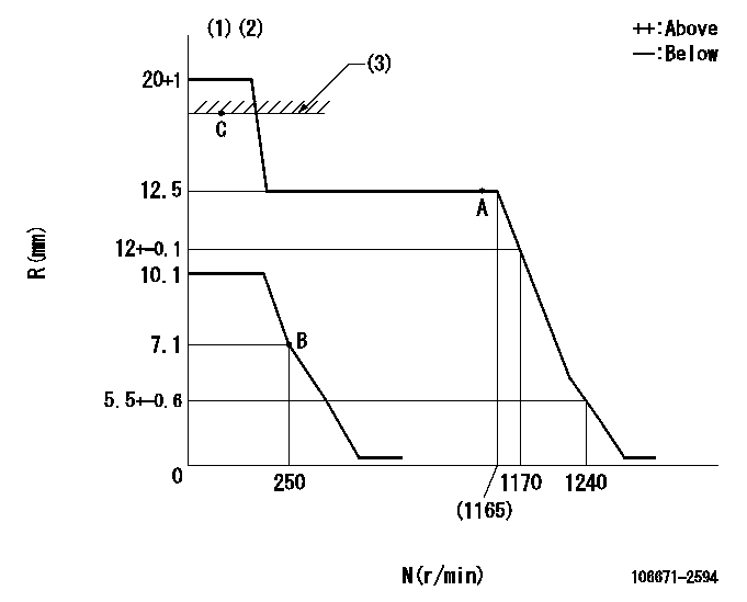
N:Pump speed
R:Rack position (mm)
(1)Target notch: K
(2)Tolerance for racks not indicated: +-0.05mm.
(3)RACK LIMIT
----------
K=17
----------
----------
K=17
----------
Speed control lever angle

F:Full speed
I:Idle
(1)Stopper bolt setting
----------
----------
a=(20deg)+-5deg b=(38deg)+-5deg
----------
----------
a=(20deg)+-5deg b=(38deg)+-5deg
Stop lever angle

N:Pump normal
S:Stop the pump.
----------
----------
a=27deg+-5deg b=53deg+-5deg
----------
----------
a=27deg+-5deg b=53deg+-5deg
Information:
Typical Example1. Loosen two bolts (2) and two nuts (3). Remove bolt (1), and remove fan drive belts (4).
Typical Example2. Remove the nuts and bolts that hold the fan drive in place. Remove fan drive (5). The following steps are for installation of the fan drive.3. Put fan drive (5) in position on the timing gear cover.4. Install bolts (2) and nuts (3) loosely. Make a replacement of the belts as a set only.5. Install fan belts (4). Install bolt (1). Make an adjustment to the belt tension with tool (A). Measure the belt farthest away from the engine. Tighten new belts to a gauge indication of 120 5. After the engine is operated at high idle for a minimum of 30 minutes, make another adjustment to the belt tension. The correct tension for used belts is a gauge indication of 90 10.6. Tighten bolts (2) and nuts (3) that hold the fan drive in place.Disassemble Fan Drive
Start By:a. remove fan drive 1. Remove two bolts (2) that hold the fan adapter to the pulley.2. Remove fan adapter (1) from the pulley 3. Remove bolts (3) and washer (4). Remove seal (5). 4. Remove pulley (8) from bracket (6).5. Remove bearing (10) and spacer (9) from the pulley. Remove spacer (7), seal (11) and bearing (12) from the pulley.Assemble Fan Drive
1. Install bearing (12) in the rear of pulley (8). 2. Install lip-type seal (11) with tooling (A). The lip of the seal must be away from the bearing. Put 5P960 Multipurpose Type Grease on the lip of the seal.3. Install spacer (7) so the end with the taper is toward the inside of pulley (8).4. Install spacer (9) and bearing (4) in the front of the pulley. 5. Put seal (5) on the front of the pulley. Install the pulley on bracket (6). 6. Install washer (4) and bolts (3) that hold the pulley in position.7. Install the fan drive adapter on the pulley.8. Fill the fan drive with 5P960 Multipurpose Type Grease.End By:a. install fan drive