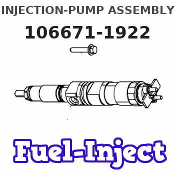
Information injection-pump assembly
ZEXEL
106671-1922
1066711922
ISUZU
1156028602
1156028602
Rating:
Cross reference number
ZEXEL
106671-1922
1066711922
ISUZU
1156028602
1156028602
Zexel num
Bosch num
Firm num
Name
Calibration Data:
Adjustment conditions
Test oil
1404 Test oil ISO4113 or {SAEJ967d}
1404 Test oil ISO4113 or {SAEJ967d}
Test oil temperature
degC
40
40
45
Nozzle and nozzle holder
105780-8250
Bosch type code
1 688 901 101
Nozzle
105780-0120
Bosch type code
1 688 901 990
Nozzle holder
105780-2190
Opening pressure
MPa
20.7
Opening pressure
kgf/cm2
211
Injection pipe
Outer diameter - inner diameter - length (mm) mm 8-3-600
Outer diameter - inner diameter - length (mm) mm 8-3-600
Overflow valve
134424-4320
Overflow valve opening pressure
kPa
255
221
289
Overflow valve opening pressure
kgf/cm2
2.6
2.25
2.95
Tester oil delivery pressure
kPa
255
255
255
Tester oil delivery pressure
kgf/cm2
1.6
1.6
1.6
RED3 control unit part number
407910-3
960
RED3 rack sensor specifications
mm
19
Direction of rotation (viewed from drive side)
Right R
Right R
Injection timing adjustment
Direction of rotation (viewed from drive side)
Right R
Right R
Injection order
1-5-3-6-
2-4
Pre-stroke
mm
5.2
5.17
5.23
Rack position
Point A R=A
Point A R=A
Beginning of injection position
Drive side NO.1
Drive side NO.1
Difference between angles 1
Cal 1-5 deg. 60 59.75 60.25
Cal 1-5 deg. 60 59.75 60.25
Difference between angles 2
Cal 1-3 deg. 120 119.75 120.25
Cal 1-3 deg. 120 119.75 120.25
Difference between angles 3
Cal 1-6 deg. 180 179.75 180.25
Cal 1-6 deg. 180 179.75 180.25
Difference between angles 4
Cyl.1-2 deg. 240 239.75 240.25
Cyl.1-2 deg. 240 239.75 240.25
Difference between angles 5
Cal 1-4 deg. 300 299.75 300.25
Cal 1-4 deg. 300 299.75 300.25
Injection quantity adjustment
Rack position
(11.6)
Vist
V
2.11
2.11
2.11
Pump speed
r/min
800
800
800
Average injection quantity
mm3/st.
136
135
137
Max. variation between cylinders
%
0
-3
3
Basic
*
Injection quantity adjustment_02
Rack position
(7)
Vist
V
2.8
2.7
2.9
Pump speed
r/min
290
290
290
Average injection quantity
mm3/st.
15
11.8
18.2
Max. variation between cylinders
%
0
-13
13
Test data Ex:
Governor adjustment

(1)Adjusting range
(2)Step response time
(N): Speed of the pump
(L): Load
(theta) Advance angle
(Srd1) Step response time 1
(Srd2) Step response time 2
1. Adjusting conditions for the variable timer
(1)Adjust the clearance between the pickup and the protrusion to L.
----------
L=1-0.2mm N2=800r/min C2=(8deg) t1=2.5--sec. t2=2.5--sec.
----------
N1=950++r/min P1=0kPa(0kgf/cm2) P2=392kPa(4kgf/cm2) C1=8+-0.3deg R01=0/4 load R02=4/4 load
----------
L=1-0.2mm N2=800r/min C2=(8deg) t1=2.5--sec. t2=2.5--sec.
----------
N1=950++r/min P1=0kPa(0kgf/cm2) P2=392kPa(4kgf/cm2) C1=8+-0.3deg R01=0/4 load R02=4/4 load
Speed control lever angle
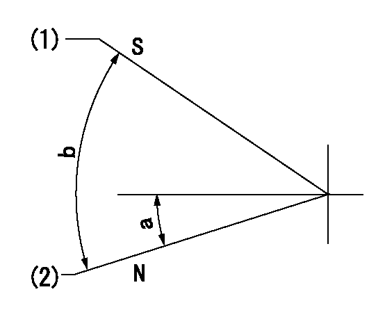
N:Pump normal
S:Stop the pump.
(1)Rack position = aa
(2)Rack position bb
----------
aa=1mm bb=20mm
----------
a=17deg+-5deg b=37deg+-5deg
----------
aa=1mm bb=20mm
----------
a=17deg+-5deg b=37deg+-5deg
0000000901

(1)Pump vertical direction
(2)Position of timer's threaded hole at No 1 cylinder's beginning of injection
(3)B.T.D.C.: aa
(4)-
----------
aa=6deg
----------
a=(100deg)
----------
aa=6deg
----------
a=(100deg)
Stop lever angle

(Rs) rack sensor specifications
(C/U) control unit part number
(V) Rack sensor output voltage
(R) Rack position (mm)
1. Confirming governor output characteristics (rack 19 mm, span 6 mm)
(1)When the output voltages of the rack sensor are V1 and V2, check that the rack positions R1 and R2 in the table above are satisfied.
----------
----------
----------
----------
Information:
1. Loosen bolts (1) and (2) on belt tightener (3), remove belt (4). 2. Loosen the hose clamp at the water temperature regulator and the water pump. Remove four bolts (5) and remove water pump. The following steps are for the installation of the water pump and belt.3. Position the water pump with two o-ring seals (6) in place. Install four bolts (5) and tighten evenly. Tighten the hose clamp at the water temperature regulator and the water pump.4. Use a breaker bar in square drive slot (7) to apply belt tension, then tighten bolts (1) and (2). To adjust belt to proper tension, see the V-Belt Tension Chart in the Specifications section of this service manual for the correct tension on the belt.End By:a. install belt (Poly-Rib) and tensionerDisassemble And Assemble Water Pump
Start By:a. remove water pump and belt 1. Remove four bolts and remove rear cover (1) with gasket from the water pump.
When pressing the water pump apart do not allow the shaft and pulley to fall to the floor, damage may occur to the pulley.
2. Position water pump in a press. Use spacer plates to level the water pump. Using a small plate from Driver Set (A), press shaft (2) and pulley (3) out of impeller (4). Remove impeller (4).3. Continue to press shaft (2) and pulley (3) out of seal (5) and the water pump housing.4. Use the handle from Driver Set (B) to remove seal (5) from the water pump housing.5. Press shaft (2) and bearing assembly from pulley (3). The following steps are for the assembly of the water pump.6. Press shaft (2) and bearing assembly into pulley (3) until the end of the shaft is flush with the pulley (as illustrated).7. Press shaft (2) and bearing assembly with pulley (3) into water pump housing to the correct pulley position (as illustrated).8. Using Water Pump Seal Installer (C), install seal (5). Press impeller (4) onto shaft (2) to the correct impeller position (as illustrated).9. Position gasket and cover (1) and install the four bolts.End By:a. install water pump and belt