Information injection-pump assembly
BOSCH
9 400 616 735
9400616735
ZEXEL
106671-1910
1066711910
ISUZU
1156029420
1156029420
Rating:
Service parts 106671-1910 INJECTION-PUMP ASSEMBLY:
1.
_
7.
COUPLING PLATE
8.
_
9.
_
11.
Nozzle and Holder
1-15300-320-0
12.
Open Pre:MPa(Kqf/cm2)
18.1{185}/22.1{225}
14.
NOZZLE
Include in #1:
106671-1910
as INJECTION-PUMP ASSEMBLY
Cross reference number
BOSCH
9 400 616 735
9400616735
ZEXEL
106671-1910
1066711910
ISUZU
1156029420
1156029420
Zexel num
Bosch num
Firm num
Name
106671-1910
9 400 616 735
1156029420 ISUZU
INJECTION-PUMP ASSEMBLY
6SD1-MTC K 14CA INJECTION PUMP ASSY PE6P,6PD PE
6SD1-MTC K 14CA INJECTION PUMP ASSY PE6P,6PD PE
Calibration Data:
Adjustment conditions
Test oil
1404 Test oil ISO4113 or {SAEJ967d}
1404 Test oil ISO4113 or {SAEJ967d}
Test oil temperature
degC
40
40
45
Nozzle and nozzle holder
105780-8140
Bosch type code
EF8511/9A
Nozzle
105780-0000
Bosch type code
DN12SD12T
Nozzle holder
105780-2080
Bosch type code
EF8511/9
Opening pressure
MPa
17.2
Opening pressure
kgf/cm2
175
Injection pipe
Outer diameter - inner diameter - length (mm) mm 8-3-600
Outer diameter - inner diameter - length (mm) mm 8-3-600
Overflow valve
134424-3920
Overflow valve opening pressure
kPa
127
107
147
Overflow valve opening pressure
kgf/cm2
1.3
1.1
1.5
Tester oil delivery pressure
kPa
157
157
157
Tester oil delivery pressure
kgf/cm2
1.6
1.6
1.6
Direction of rotation (viewed from drive side)
Left L
Left L
Injection timing adjustment
Direction of rotation (viewed from drive side)
Left L
Left L
Injection order
1-5-3-6-
2-4
Pre-stroke
mm
4.2
4.17
4.23
Beginning of injection position
Governor side NO.1
Governor side NO.1
Difference between angles 1
Cal 1-5 deg. 60 59.75 60.25
Cal 1-5 deg. 60 59.75 60.25
Difference between angles 2
Cal 1-3 deg. 120 119.75 120.25
Cal 1-3 deg. 120 119.75 120.25
Difference between angles 3
Cal 1-6 deg. 180 179.75 180.25
Cal 1-6 deg. 180 179.75 180.25
Difference between angles 4
Cyl.1-2 deg. 240 239.75 240.25
Cyl.1-2 deg. 240 239.75 240.25
Difference between angles 5
Cal 1-4 deg. 300 299.75 300.25
Cal 1-4 deg. 300 299.75 300.25
Injection quantity adjustment
Adjusting point
A
Rack position
12
Pump speed
r/min
1150
1150
1150
Average injection quantity
mm3/st.
220
218
222
Max. variation between cylinders
%
0
-2.5
2.5
Basic
*
Fixing the lever
*
Boost pressure
kPa
106.6
106.6
Boost pressure
mmHg
800
800
Injection quantity adjustment_02
Adjusting point
B
Rack position
6+-0.5
Pump speed
r/min
275
275
275
Average injection quantity
mm3/st.
14
12
16
Max. variation between cylinders
%
0
-14
14
Fixing the rack
*
Boost pressure
kPa
0
0
0
Boost pressure
mmHg
0
0
0
Boost compensator adjustment
Pump speed
r/min
650
650
650
Rack position
10.4
Boost pressure
kPa
45.3
42.6
48
Boost pressure
mmHg
340
320
360
Boost compensator adjustment_02
Pump speed
r/min
650
650
650
Rack position
12
Boost pressure
kPa
93.3
93.3
93.3
Boost pressure
mmHg
700
700
700
Timer adjustment
Pump speed
r/min
1150++
Advance angle
deg.
0
0
0
Remarks
Do not advance until starting N = 1150.
Do not advance until starting N = 1150.
Timer adjustment_02
Pump speed
r/min
-
Advance angle
deg.
0.5
0.5
0.5
Remarks
Measure the actual speed, stop
Measure the actual speed, stop
Test data Ex:
Governor adjustment

N:Pump speed
R:Rack position (mm)
(1)Lever ratio: RT
(2)Target shim dimension: TH
(3)Tolerance for racks not indicated: +-0.05mm.
(4)Boost compensator excessive fuel lever setting: L1 (at boost pressure 0)
(5)Boost compensator stroke: BCL
(6)Set idle sub-spring
(7)Main spring setting
(8)Damper spring setting
----------
RT=1 TH=2.5mm L1=12.2+0.2mm BCL=1.6+-0.1mm
----------
----------
RT=1 TH=2.5mm L1=12.2+0.2mm BCL=1.6+-0.1mm
----------
Speed control lever angle
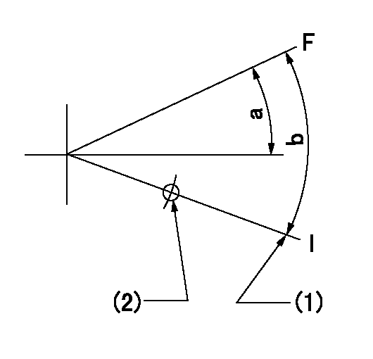
F:Full speed
I:Idle
(1)Stopper bolt setting
(2)Use the hole at R = aa
----------
aa=85mm
----------
a=9.5deg+-5deg b=16deg+-5deg
----------
aa=85mm
----------
a=9.5deg+-5deg b=16deg+-5deg
0000000901
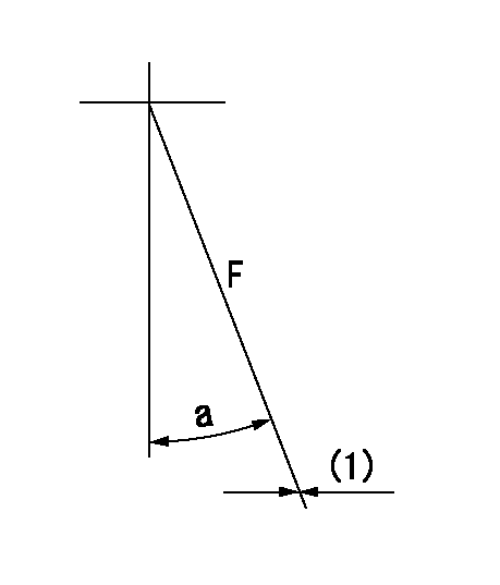
F:Full load
(1)Fix using the stopper bolt.
----------
----------
a=(31deg)+-5deg
----------
----------
a=(31deg)+-5deg
Stop lever angle

N:Pump normal
S:Stop the pump.
(1)Drive side
----------
----------
a=32deg+-5deg b=64deg+-5deg
----------
----------
a=32deg+-5deg b=64deg+-5deg
0000001101
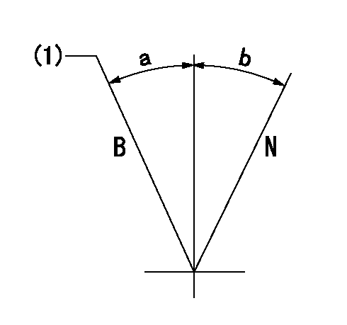
N:Normal
B:When boosted
(1)Rack position = aa at boost pressure 0.
----------
aa=12.2+0.2mm
----------
a=(15deg) b=(15deg)
----------
aa=12.2+0.2mm
----------
a=(15deg) b=(15deg)
Timing setting

(1)Pump vertical direction
(2)Position of timer's threaded hole at No 1 cylinder's beginning of injection
(3)B.T.D.C.: aa
(4)-
----------
aa=14deg
----------
a=(40deg)
----------
aa=14deg
----------
a=(40deg)
Information:
8T0900 AC/DC Clamp-On AmmeterThe 8T0900 AC/DC Clamp-On Ammeter is a completely portable, self-contained instrument that allows electrical current measurements to be made without breaking the circuit or disturbing the insulation on conductors. A digital display is located on the ammeter for reading current directly in a range from 1 to 1200 amperes. If a optional 6V6014 Cable is connected between this ammeter and one of the digital multimeters, current readings of less than 1 ammeter can then be read directly from the display of the multimeter.A lever is used to open the jaws over the conductor [up to a diameter of 19 mm (.75 in)], and the spring loaded jaws are then closed around the conductor for current measurement. A trigger switch that can be locked in the ON or OFF position is used to turn on the ammeter. When the turn-on trigger is released, the last current reading is held on the display for 5 seconds. This allows accurate measurements to be taken in limited access areas where the digital display is not visible to the operator. A zero control is provided for DC operation, and power for the ammeter is supplied by batteries located inside the handle. Make reference to Special Instruction, Form No. SEHS8420 for more complete information for use of the 8T0900 Clamp-On Ammeter.
6V7070 Heavy-Duty Digital MultimeterThe 6V7070 Heavy-Duty Digital Multimeter is a completely portable, hand held instrument with a digital display. This multimeter is built with extra protection against damage in field applications, and is equipped with seven functions and 29 ranges. The 6V7070 Multimeter has an instant ohms indicator that permits continuity checking for fast circuit inspection. It also can be used for troubleshooting small value capacitors.The 6V7800 Regular-duty Digital Multimeter (a low cost option to the Heavy-Duty Multimeter) is also available; however, the 6V7800 Multimeter does not have the 10A range or the instant ohms feature of the 6V7070 Multimeter. Make reference to Special Instruction, Form No. SEHS7734 for more complete information for use of the 6V7070 and 6V7800 Multimeters.Battery
Never disconnect any charging unit circuit or battery circuit cable from battery when the charging unit is operated. A spark can cause an explosion from the flammable vapor mixture of hydrogen and oxygen that is released from the electrolyte through the battery outlets. Injury to personnel can be the result.
The battery circuit is an electrical load on the charging unit. The load is variable because of the condition of the charge in the battery. Damage to the charging unit will result if the connections (either positive or negative) between the battery and charging unit are broken while the charging unit is in operation. This is because the battery load is lost and there is an increase in charging voltage. High voltage will damage, not only the charging unit, but also the regulator and other electrical components.Use the 6V4930 Battery Load Tester, the 8T900 Clamp-On Ammeter and the 6V7070 Multimeter to load test a battery that does not hold a charge when in
Have questions with 106671-1910?
Group cross 106671-1910 ZEXEL
Isuzu
106671-1910
9 400 616 735
1156029420
INJECTION-PUMP ASSEMBLY
6SD1-MTC
6SD1-MTC