Information injection-pump assembly
BOSCH
9 400 616 734
9400616734
ZEXEL
106671-1900
1066711900
ISUZU
1156028990
1156028990
Rating:
Service parts 106671-1900 INJECTION-PUMP ASSEMBLY:
1.
_
7.
COUPLING PLATE
8.
_
9.
_
11.
Nozzle and Holder
1-15300-320-0
12.
Open Pre:MPa(Kqf/cm2)
18.1{185}/22.1{225}
14.
NOZZLE
Include in #1:
106671-1900
as INJECTION-PUMP ASSEMBLY
Cross reference number
BOSCH
9 400 616 734
9400616734
ZEXEL
106671-1900
1066711900
ISUZU
1156028990
1156028990
Zexel num
Bosch num
Firm num
Name
9 400 616 734
1156028990 ISUZU
INJECTION-PUMP ASSEMBLY
6SD1-MTC * K 14CA INJECTION PUMP ASSY PE6P,6PD PE
6SD1-MTC * K 14CA INJECTION PUMP ASSY PE6P,6PD PE
Calibration Data:
Adjustment conditions
Test oil
1404 Test oil ISO4113 or {SAEJ967d}
1404 Test oil ISO4113 or {SAEJ967d}
Test oil temperature
degC
40
40
45
Nozzle and nozzle holder
105780-8140
Bosch type code
EF8511/9A
Nozzle
105780-0000
Bosch type code
DN12SD12T
Nozzle holder
105780-2080
Bosch type code
EF8511/9
Opening pressure
MPa
17.2
Opening pressure
kgf/cm2
175
Injection pipe
Outer diameter - inner diameter - length (mm) mm 8-3-600
Outer diameter - inner diameter - length (mm) mm 8-3-600
Overflow valve
134424-3920
Overflow valve opening pressure
kPa
127
107
147
Overflow valve opening pressure
kgf/cm2
1.3
1.1
1.5
Tester oil delivery pressure
kPa
157
157
157
Tester oil delivery pressure
kgf/cm2
1.6
1.6
1.6
Direction of rotation (viewed from drive side)
Left L
Left L
Injection timing adjustment
Direction of rotation (viewed from drive side)
Left L
Left L
Injection order
1-5-3-6-
2-4
Pre-stroke
mm
4.2
4.17
4.23
Beginning of injection position
Governor side NO.1
Governor side NO.1
Difference between angles 1
Cal 1-5 deg. 60 59.75 60.25
Cal 1-5 deg. 60 59.75 60.25
Difference between angles 2
Cal 1-3 deg. 120 119.75 120.25
Cal 1-3 deg. 120 119.75 120.25
Difference between angles 3
Cal 1-6 deg. 180 179.75 180.25
Cal 1-6 deg. 180 179.75 180.25
Difference between angles 4
Cyl.1-2 deg. 240 239.75 240.25
Cyl.1-2 deg. 240 239.75 240.25
Difference between angles 5
Cal 1-4 deg. 300 299.75 300.25
Cal 1-4 deg. 300 299.75 300.25
Injection quantity adjustment
Adjusting point
A
Rack position
12
Pump speed
r/min
1150
1150
1150
Average injection quantity
mm3/st.
220
218
222
Max. variation between cylinders
%
0
-2.5
2.5
Basic
*
Fixing the lever
*
Boost pressure
kPa
106.6
106.6
Boost pressure
mmHg
800
800
Injection quantity adjustment_02
Adjusting point
B
Rack position
6+-0.5
Pump speed
r/min
275
275
275
Average injection quantity
mm3/st.
14
12
16
Max. variation between cylinders
%
0
-14
14
Fixing the rack
*
Boost pressure
kPa
0
0
0
Boost pressure
mmHg
0
0
0
Boost compensator adjustment
Pump speed
r/min
650
650
650
Rack position
10.4
Boost pressure
kPa
45.3
42.6
48
Boost pressure
mmHg
340
320
360
Boost compensator adjustment_02
Pump speed
r/min
650
650
650
Rack position
12
Boost pressure
kPa
93.3
93.3
93.3
Boost pressure
mmHg
700
700
700
Timer adjustment
Pump speed
r/min
1150++
Advance angle
deg.
0
0
0
Remarks
Do not advance until starting N = 1150.
Do not advance until starting N = 1150.
Timer adjustment_02
Pump speed
r/min
-
Advance angle
deg.
0.5
0.5
0.5
Remarks
Measure the actual speed, stop
Measure the actual speed, stop
Test data Ex:
Governor adjustment
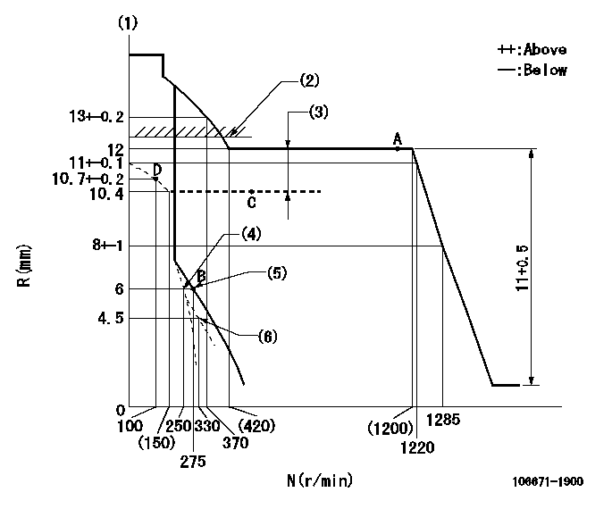
N:Pump speed
R:Rack position (mm)
(1)Tolerance for racks not indicated: +-0.05mm.
(2)Boost compensator excessive fuel lever setting: L1 (at boost pressure 0)
(3)Boost compensator stroke: BCL
(4)Set idle sub-spring
(5)Main spring setting
(6)Damper spring setting
----------
L1=12.2+0.2mm BCL=1.6+-0.1mm
----------
----------
L1=12.2+0.2mm BCL=1.6+-0.1mm
----------
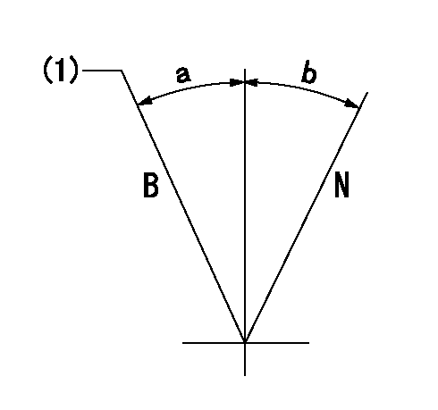
Speed control lever angle
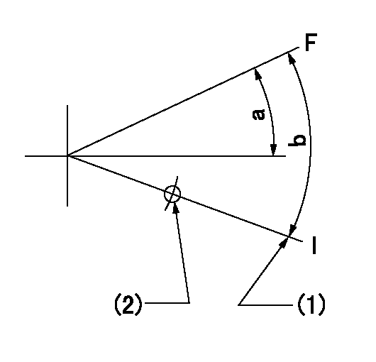
F:Full speed
I:Idle
(1)Stopper bolt setting
(2)Use the hole at R = aa
----------
aa=85mm
----------
a=9.5deg+-5deg b=16deg+-5deg
----------
aa=85mm
----------
a=9.5deg+-5deg b=16deg+-5deg
0000000901
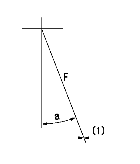
F:Full load
(1)Fix using the stopper bolt.
----------
----------
a=(31deg)+-5deg
----------
----------
a=(31deg)+-5deg
Stop lever angle

N:Pump normal
S:Stop the pump.
(1)Drive side
----------
----------
a=32deg+-5deg b=64deg+-5deg
----------
----------
a=32deg+-5deg b=64deg+-5deg
0000001101
N:Normal
B:When boosted
(1)Rack position = aa (at boost pressure = bb)
----------
aa=12.2+0.2mm bb=0kPa(0mmHg)
----------
a=(15deg) b=(15deg)
----------
aa=12.2+0.2mm bb=0kPa(0mmHg)
----------
a=(15deg) b=(15deg)
Timing setting

(1)Pump vertical direction
(2)Position of timer's threaded hole at No 1 cylinder's beginning of injection
(3)B.T.D.C.: aa
(4)-
----------
aa=14deg
----------
a=(40deg)
----------
aa=14deg
----------
a=(40deg)
Information:
Charging System Components
Alternator
Alternator Components (Typical Example)
(1) Brush holder. (2) Rear frame. (3) Rotor. (4) Stator. (5) Drive end frame. (6) Fan assembly. (7) Slip rings. (8) Rectifier.The alternator used on the 3116 Truck Engines has three phase, full-wave, rectified output. It is a brush type alternator.The alternator is an electrical and mechanical component driven by a belt from engine rotation. It is used to charge the storage battery during engine operation. The alternator is cooled by a fan that is a part of the alternator. The fan pulls air through holes in the back of the alternator. The air exists the front of the alternator, cooling it in the process.The alternator converts mechanical and magnetic energy to alternating current (AC) and voltage. This process is done by rotating a direct current (DC) electromagnetic field (rotor) inside a three phase stator. The alternating current and voltage (generated by the stator) are changed to direct current by a three phase, full wave rectifier system using six silicone rectifier diodes. The alternator also has a diode trio which is an assembly made up of three exciter diodes. The diode trio rectifies field current needed to start the charging process. Direct current flows to the alternator output terminal.A solid state regulator is installed in the back of the alternator. Two brushes conduct current, through two slip rings, to the field coil on the rotor.There is also a capicitor mounted in the back of the alternator. The capacitor protects the rectifier from high voltages. It also suppresses radio noise.Regulator
The voltage regulator is a solid state (transistor, stationary parts) electronic switch which controls the alternator output. The regulator limits the alternator voltage to a preset value by controlling the field current. It feels the voltage in the system and switches "ON" and "OFF" many times a second to control the field current (DC current to the field windings) for the alternator to make the needed voltage output. Refer to Service Manual, Form No. SENR3862, for detailed service information for the Delco Remy 21 SI Series Alternator. For engines which have the alternator connected to an engine component, the ground strap must connect that component to the frame or to the battery ground.Starting System Components
Starter Solenoid
A solenoid is a magnetic switch that does two basic operations:1. Closes the high current starter motor circuit with a low current start switch circuit.2. Engages the starter motor pinion with the ring gear.
Typical SolenoidThe solenoid switch is made of an electromagnet (one or two sets of windings) around a hollow cylinder. There is a plunger (core) with a spring load inside the cylinder that can move forward and backward. When the start switch is closed and electricity is sent through the windings, a magnetic field is made that pulls the plunger forward in the cylinder. This moves the shift lever (connected to the rear of the plunger) to engage the pinion drive gear with the ring gear. The front end of the plunger then makes contact across the battery