Information injection-pump assembly
BOSCH
9 400 619 690
9400619690
ZEXEL
106671-1830
1066711830

Rating:
Service parts 106671-1830 INJECTION-PUMP ASSEMBLY:
1.
_
7.
COUPLING PLATE
8.
_
9.
_
11.
Nozzle and Holder
1-15300-303-2
12.
Open Pre:MPa(Kqf/cm2)
19.6{200}
15.
NOZZLE SET
Include in #1:
106671-1830
as INJECTION-PUMP ASSEMBLY
Cross reference number
BOSCH
9 400 619 690
9400619690
ZEXEL
106671-1830
1066711830
Zexel num
Bosch num
Firm num
Name
Calibration Data:
Adjustment conditions
Test oil
1404 Test oil ISO4113 or {SAEJ967d}
1404 Test oil ISO4113 or {SAEJ967d}
Test oil temperature
degC
40
40
45
Nozzle and nozzle holder
105780-8130
Bosch type code
EFEP215A
Nozzle
105780-0050
Bosch type code
DN6TD119NP1T
Nozzle holder
105780-2090
Bosch type code
EFEP215
Opening pressure
MPa
17.2
Opening pressure
kgf/cm2
175
Injection pipe
Outer diameter - inner diameter - length (mm) mm 8-3-600
Outer diameter - inner diameter - length (mm) mm 8-3-600
Overflow valve
134424-3920
Overflow valve opening pressure
kPa
127
107
147
Overflow valve opening pressure
kgf/cm2
1.3
1.1
1.5
Tester oil delivery pressure
kPa
157
157
157
Tester oil delivery pressure
kgf/cm2
1.6
1.6
1.6
Direction of rotation (viewed from drive side)
Right R
Right R
Injection timing adjustment
Direction of rotation (viewed from drive side)
Right R
Right R
Injection order
1-4-2-6-
3-5
Pre-stroke
mm
4.2
4.15
4.25
Beginning of injection position
Drive side NO.1
Drive side NO.1
Difference between angles 1
Cal 1-4 deg. 60 59.5 60.5
Cal 1-4 deg. 60 59.5 60.5
Difference between angles 2
Cyl.1-2 deg. 120 119.5 120.5
Cyl.1-2 deg. 120 119.5 120.5
Difference between angles 3
Cal 1-6 deg. 180 179.5 180.5
Cal 1-6 deg. 180 179.5 180.5
Difference between angles 4
Cal 1-3 deg. 240 239.5 240.5
Cal 1-3 deg. 240 239.5 240.5
Difference between angles 5
Cal 1-5 deg. 300 299.5 300.5
Cal 1-5 deg. 300 299.5 300.5
Injection quantity adjustment
Adjusting point
A
Rack position
12
Pump speed
r/min
1000
1000
1000
Average injection quantity
mm3/st.
434
431
437
Max. variation between cylinders
%
0
-3
3
Basic
*
Fixing the lever
*
Boost pressure
kPa
173.3
173.3
Boost pressure
mmHg
1300
1300
Injection quantity adjustment_02
Adjusting point
B
Rack position
4+-0.5
Pump speed
r/min
300
300
300
Average injection quantity
mm3/st.
8
4.8
11.2
Max. variation between cylinders
%
0
-13
13
Fixing the rack
*
Boost pressure
kPa
0
0
0
Boost pressure
mmHg
0
0
0
Injection quantity adjustment_03
Adjusting point
C
Rack position
8.3
Pump speed
r/min
500
500
500
Average injection quantity
mm3/st.
225.5
222.5
228.5
Fixing the lever
*
Boost pressure
kPa
0
0
0
Boost pressure
mmHg
0
0
0
Boost compensator adjustment
Pump speed
r/min
500
500
500
Rack position
8.3
Boost pressure
kPa
26.7
25.4
28
Boost pressure
mmHg
200
190
210
Boost compensator adjustment_02
Pump speed
r/min
500
500
500
Rack position
(12)
Boost pressure
kPa
149.3
149.3
149.3
Boost pressure
mmHg
1120
1120
1120
Timer adjustment
Pump speed
r/min
1050++
Advance angle
deg.
0
0
0
Remarks
Do not advance until starting N = 1050.
Do not advance until starting N = 1050.
Timer adjustment_02
Pump speed
r/min
-
Advance angle
deg.
1
1
1
Remarks
Measure the actual speed, stop
Measure the actual speed, stop
Test data Ex:
Governor adjustment
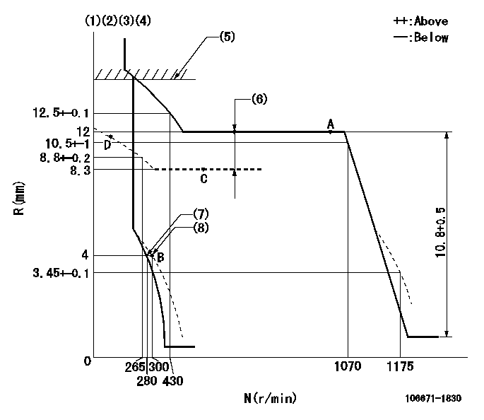
N:Pump speed
R:Rack position (mm)
(1)Lever ratio: RT
(2)Target shim dimension: TH
(3)Tolerance for racks not indicated: +-0.05mm.
(4)Deliver with the damper spring not operating.
(5)Boost compensator excessive fuel lever setting: L1 (at boost pressure 0)
(6)Boost compensator stroke: BCL
(7)Main spring setting
(8)Set idle sub-spring
----------
RT=1 TH=2.5mm L1=13.6+-0.1mm BCL=(3.7)+-0.1mm
----------
----------
RT=1 TH=2.5mm L1=13.6+-0.1mm BCL=(3.7)+-0.1mm
----------
Speed control lever angle
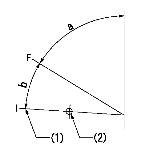
F:Full speed
I:Idle
(1)Stopper bolt setting
(2)Use the hole at R = aa
----------
aa=85.1mm
----------
a=72.5deg+-5deg b=15deg+-5deg
----------
aa=85.1mm
----------
a=72.5deg+-5deg b=15deg+-5deg
0000000901
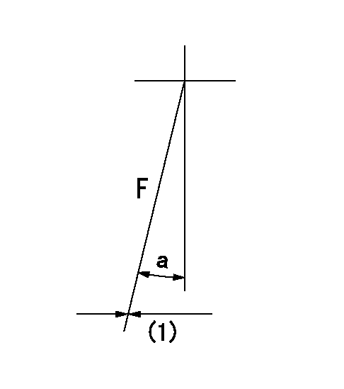
F:Full load
(1)Fix using the stopper bolt.
----------
----------
a=(19deg)+-5deg
----------
----------
a=(19deg)+-5deg
Stop lever angle
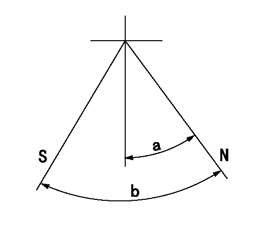
N:Pump normal
S:Stop the pump.
----------
----------
a=32deg+-5deg b=64deg+-5deg
----------
----------
a=32deg+-5deg b=64deg+-5deg
0000001101
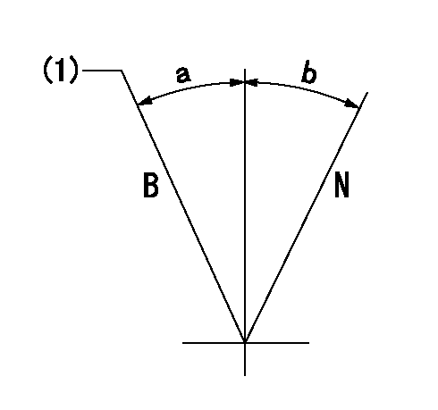
N:Normal
B:When boosted
(1)Rack position = aa at boost pressure 0.
----------
aa=13.6+-0.1mm
----------
a=(15deg) b=(15deg)
----------
aa=13.6+-0.1mm
----------
a=(15deg) b=(15deg)
Timing setting

(1)Pump vertical direction
(2)Position of timer's threaded hole at No 1 cylinder's beginning of injection
(3)B.T.D.C.: aa
(4)-
----------
aa=15deg
----------
a=(70deg)
----------
aa=15deg
----------
a=(70deg)
Information:
Start By:a. remove flywheel housingb. remove oil pan platec. remove camshaft
Keep all parts clean from contaminants. Contaminants put into the system may cause rapid wear and shortened component life.
1. Remove the camshaft bearings from the cylinder block with tooling (A). Start with the front bearing and work to the rear. The following steps are for the installation of the camshaft bearings.2. Use tooling (A) to install the camshaft bearings in the cylinder block. 3. Install the camshaft bearings in the cylinder block as follows:a. Install the front bearing to a depth of 0.5 0.5 mm (.02 .02 in) and with the oil holes in a horizontal position and the joint at the top of the engine. The joint can not be more than 15° from vertical in either direction.b. Install the remainder of the bearings. Install the bearings to the dimensions given from the front face of the cylinder block: A) 154.0 0.5 mm (6.06 .02 in), B) 303.2 0.5 mm (11.94 .02 in), C) 601.7 0.5 mm (23.69 .02 in), D) 903.4 0.5 mm (35.57 .02 in).End By:a. install camshaftb. install oil pan platec. install flywheel housing
Perform Scheduled Oil Sampling on oil wetted compartments after performing service work to check for contaminants left in the system following repair. Contaminants put into the system may cause rapid wear and shortened component life.