Information injection-pump assembly
ZEXEL
106671-1813
1066711813
ISUZU
1156028183
1156028183
Rating:
Service parts 106671-1813 INJECTION-PUMP ASSEMBLY:
1.
_
7.
COUPLING PLATE
8.
_
9.
_
11.
Nozzle and Holder
1-15300-351-0
12.
Open Pre:MPa(Kqf/cm2)
17.7{180}/23.5{240}
15.
NOZZLE SET
Include in #1:
106671-1813
as INJECTION-PUMP ASSEMBLY
Cross reference number
ZEXEL
106671-1813
1066711813
ISUZU
1156028183
1156028183
Zexel num
Bosch num
Firm num
Name
Calibration Data:
Adjustment conditions
Test oil
1404 Test oil ISO4113 or {SAEJ967d}
1404 Test oil ISO4113 or {SAEJ967d}
Test oil temperature
degC
40
40
45
Nozzle and nozzle holder
105780-8140
Bosch type code
EF8511/9A
Nozzle
105780-0000
Bosch type code
DN12SD12T
Nozzle holder
105780-2080
Bosch type code
EF8511/9
Opening pressure
MPa
17.2
Opening pressure
kgf/cm2
175
Injection pipe
Outer diameter - inner diameter - length (mm) mm 8-3-600
Outer diameter - inner diameter - length (mm) mm 8-3-600
Overflow valve
134424-4320
Overflow valve opening pressure
kPa
255
221
289
Overflow valve opening pressure
kgf/cm2
2.6
2.25
2.95
Tester oil delivery pressure
kPa
157
157
157
Tester oil delivery pressure
kgf/cm2
1.6
1.6
1.6
Direction of rotation (viewed from drive side)
Right R
Right R
Injection timing adjustment
Direction of rotation (viewed from drive side)
Right R
Right R
Injection order
1-5-3-6-
2-4
Pre-stroke
mm
3.8
3.77
3.83
Beginning of injection position
Drive side NO.1
Drive side NO.1
Difference between angles 1
Cal 1-5 deg. 60 59.75 60.25
Cal 1-5 deg. 60 59.75 60.25
Difference between angles 2
Cal 1-3 deg. 120 119.75 120.25
Cal 1-3 deg. 120 119.75 120.25
Difference between angles 3
Cal 1-6 deg. 180 179.75 180.25
Cal 1-6 deg. 180 179.75 180.25
Difference between angles 4
Cyl.1-2 deg. 240 239.75 240.25
Cyl.1-2 deg. 240 239.75 240.25
Difference between angles 5
Cal 1-4 deg. 300 299.75 300.25
Cal 1-4 deg. 300 299.75 300.25
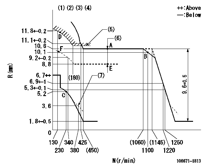
Injection quantity adjustment
Adjusting point
A
Rack position
10.6
Pump speed
r/min
700
700
700
Average injection quantity
mm3/st.
172.5
170.5
174.5
Max. variation between cylinders
%
0
-3
3
Basic
*
Fixing the lever
*
Boost pressure
kPa
34
34
Boost pressure
mmHg
255
255
Injection quantity adjustment_02
Adjusting point
B
Rack position
10.1
Pump speed
r/min
1100
1100
1100
Average injection quantity
mm3/st.
166.5
160.5
172.5
Fixing the lever
*
Boost pressure
kPa
34
34
Boost pressure
mmHg
255
255
Injection quantity adjustment_03
Adjusting point
C
Rack position
5.2+-0.5
Pump speed
r/min
230
230
230
Average injection quantity
mm3/st.
11.5
8.3
14.7
Max. variation between cylinders
%
0
-13
13
Fixing the rack
*
Boost pressure
kPa
0
0
0
Boost pressure
mmHg
0
0
0
Injection quantity adjustment_04
Adjusting point
D
Rack position
-
Pump speed
r/min
150
150
150
Average injection quantity
mm3/st.
160
160
Fixing the lever
*
Boost pressure
kPa
34
34
Boost pressure
mmHg
255
255
Remarks
After startup boost setting
After startup boost setting
Injection quantity adjustment_05
Adjusting point
E
Rack position
8.8
Pump speed
r/min
700
700
700
Average injection quantity
mm3/st.
126.5
123.5
129.5
Fixing the lever
*
Boost pressure
kPa
0
0
0
Boost pressure
mmHg
0
0
0
Boost compensator adjustment
Pump speed
r/min
700
700
700
Rack position
8.8
Boost pressure
kPa
7.3
7.3
8.6
Boost pressure
mmHg
55
55
65
Boost compensator adjustment_02
Pump speed
r/min
700
700
700
Rack position
10.6
Boost pressure
kPa
20.7
20.7
20.7
Boost pressure
mmHg
155
155
155
Test data Ex:
Governor adjustment
N:Pump speed
R:Rack position (mm)
(1)Lever ratio: RT
(2)Target shim dimension: TH
(3)Tolerance for racks not indicated: +-0.05mm.
(4)Deliver without the torque control spring operating.
(5)Excess fuel setting for starting: SXL (N = N1)
(6)Boost compensator stroke: BCL
(7)Damper spring setting
----------
RT=1 TH=3mm SXL=11.5+-0.1mm N1=350r/min BCL=1.8+-0.1mm
----------
----------
RT=1 TH=3mm SXL=11.5+-0.1mm N1=350r/min BCL=1.8+-0.1mm
----------
Timer adjustment

(1)Adjusting range
(2)Step response time
(N): Speed of the pump
(L): Load
(theta) Advance angle
(Srd1) Step response time 1
(Srd2) Step response time 2
1. Adjusting conditions for the variable timer
(1)Adjust the clearance between the pickup and the protrusion to L.
----------
L=1-0.2mm N2=800r/min C2=(8)deg t1=1.7--sec. t2=1.7--sec.
----------
N1=950++r/min P1=0kPa(0kgf/cm2) P2=392kPa(4kgf/cm2) C1=8+-0.3deg R01=0/4load R02=4/4load
----------
L=1-0.2mm N2=800r/min C2=(8)deg t1=1.7--sec. t2=1.7--sec.
----------
N1=950++r/min P1=0kPa(0kgf/cm2) P2=392kPa(4kgf/cm2) C1=8+-0.3deg R01=0/4load R02=4/4load
Speed control lever angle

F:Full speed
----------
----------
a=3deg+-5deg
----------
----------
a=3deg+-5deg
0000000901
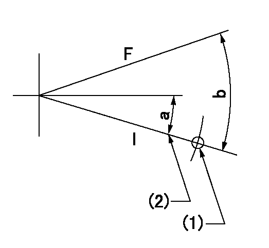
F:Full load
I:Idle
(1)Use the hole at R = aa
(2)Stopper bolt setting
----------
aa=33mm
----------
a=15deg+-5deg b=32.5deg+-3deg
----------
aa=33mm
----------
a=15deg+-5deg b=32.5deg+-3deg
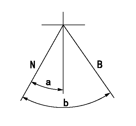
Stop lever angle
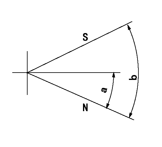
N:Pump normal
S:Stop the pump.
----------
----------
a=37deg+-5deg b=73deg+-5deg
----------
----------
a=37deg+-5deg b=73deg+-5deg
0000001101
N:Normal
B:When boosted
----------
----------
a=3deg+-5deg b=16.5deg+-5deg
----------
----------
a=3deg+-5deg b=16.5deg+-5deg
0000001501 RACK SENSOR

(VR) measurement voltage
(I) Part number of the control unit
(G) Apply red paint.
(H): End surface of the pump
1. Rack sensor adjustment (-0620)
(1)Fix the speed control lever at the full position
(2)Set the speed to N1 r/min.
(If the boost compensator is provided, apply boost pressure.)
(3)Adjust the bobbin (A) so that the rack sensor's output voltage is VR+-0.01.
(4)At that time, rack position must be Ra.
(5)Apply G at two places.
Connecting part between the joint (B) and the nut (F)
Connecting part between the joint (B) and the end surface of the pump (H)
----------
N1=700r/min Ra=10.6mm
----------
----------
N1=700r/min Ra=10.6mm
----------
Timing setting

(1)Pump vertical direction
(2)Position of timer's threaded hole at No 1 cylinder's beginning of injection
(3)-
(4)-
----------
----------
a=(100deg)
----------
----------
a=(100deg)
Information:
Start By:a. remove oil pumpb. remove oil pan plate
Keep all parts clean from contaminants. Contaminants put into the system may cause rapid wear and shortened component life.
1. Turn the crankshaft until two pistons are at the bottom center. Remove connecting rod caps (1) from the two connecting rods. Remove the lower half of the rod bearing from the rod bearing cap.
The connecting rod bolts are loose on the connecting rods and can fall out when the nuts are removed.
2. Push the connecting rods away from the crankshaft. Remove the upper half of the rod bearing from the connecting rod. Install the connecting rod bearings dry when the clearance checks are made. Put clean engine oil on the connecting rod bearings for final assembly.3. Install the upper half of the rod bearing in the connecting rod.4. Install the lower half of the rod bearing in the connecting rod cap. Be sure the tabs in the back of the connecting rod bearings are in the tab grooves of the connecting rod and cap. 5. Use Plastigage (A) to check the connecting rod bearing clearance.6. Put Plastigage (A) on the connecting rod bearing.7. Put 2P2506 Thread Lubricant on the threads of the rod bolts and seat surfaces of the nuts.
When connecting rod caps are installed, make sure the number on the side of the cap is next to and respective with the number on the side of the connecting rod.
Do not turn the crankshaft when Plastigage (A) is in position.
Do not use an impact wrench to tighten the nuts the additional 90°.
8. Install connecting rod cap (1). Install the nuts. Tighten the nuts to a torque of 40 4 N m (30 3 lb ft) Put a mark on each nut and the end of each bolt. Tighten the nuts 90° more. Remove the connecting rod caps. Remove Plastigage (A) and measure the width of the Plastigage. The connecting rod clearance must be 0.076 to 0.168 mm (.0030 to .0066 in) for new bearings. The maximum clearance with used bearings is 0.25 mm (.010 in).9. Install the connecting rod caps and tighten the nuts as in Step 8.10. Do Steps 1 through 9 for the remainder of the connecting rod bearings.End By:a. install oil pan plateb. install oil pump
Perform Scheduled Oil Sampling on oil wetted compartments after performing service work to check for contaminants left in the system following repair. Contaminants put into the system may cause rapid wear and shortened component life.