Information injection-pump assembly
BOSCH
9 400 610 324
9400610324
ZEXEL
106671-1481
1066711481
ISUZU
1156023201
1156023201
Rating:
Service parts 106671-1481 INJECTION-PUMP ASSEMBLY:
1.
_
7.
COUPLING PLATE
8.
_
9.
_
11.
Nozzle and Holder
1-15300-159-1
12.
Open Pre:MPa(Kqf/cm2)
19.6{200}
15.
NOZZLE SET
Include in #1:
106671-1481
as INJECTION-PUMP ASSEMBLY
Cross reference number
BOSCH
9 400 610 324
9400610324
ZEXEL
106671-1481
1066711481
ISUZU
1156023201
1156023201
Zexel num
Bosch num
Firm num
Name
106671-1481
9 400 610 324
1156023201 ISUZU
INJECTION-PUMP ASSEMBLY
6RB1T K 14CA INJECTION PUMP ASSY PE6P,6PD PE
6RB1T K 14CA INJECTION PUMP ASSY PE6P,6PD PE
Calibration Data:
Adjustment conditions
Test oil
1404 Test oil ISO4113 or {SAEJ967d}
1404 Test oil ISO4113 or {SAEJ967d}
Test oil temperature
degC
40
40
45
Nozzle and nozzle holder
105780-8140
Bosch type code
EF8511/9A
Nozzle
105780-0000
Bosch type code
DN12SD12T
Nozzle holder
105780-2080
Bosch type code
EF8511/9
Opening pressure
MPa
17.2
Opening pressure
kgf/cm2
175
Injection pipe
Outer diameter - inner diameter - length (mm) mm 8-3-600
Outer diameter - inner diameter - length (mm) mm 8-3-600
Overflow valve
134424-1920
Overflow valve opening pressure
kPa
127
107
147
Overflow valve opening pressure
kgf/cm2
1.3
1.1
1.5
Tester oil delivery pressure
kPa
157
157
157
Tester oil delivery pressure
kgf/cm2
1.6
1.6
1.6
Direction of rotation (viewed from drive side)
Right R
Right R
Injection timing adjustment
Direction of rotation (viewed from drive side)
Right R
Right R
Injection order
1-4-2-6-
3-5
Pre-stroke
mm
3.8
3.77
3.83
Beginning of injection position
Drive side NO.1
Drive side NO.1
Difference between angles 1
Cal 1-4 deg. 60 59.75 60.25
Cal 1-4 deg. 60 59.75 60.25
Difference between angles 2
Cyl.1-2 deg. 120 119.75 120.25
Cyl.1-2 deg. 120 119.75 120.25
Difference between angles 3
Cal 1-6 deg. 180 179.75 180.25
Cal 1-6 deg. 180 179.75 180.25
Difference between angles 4
Cal 1-3 deg. 240 239.75 240.25
Cal 1-3 deg. 240 239.75 240.25
Difference between angles 5
Cal 1-5 deg. 300 299.75 300.25
Cal 1-5 deg. 300 299.75 300.25
Injection quantity adjustment
Adjusting point
A
Rack position
8.2
Pump speed
r/min
1000
1000
1000
Average injection quantity
mm3/st.
156.6
154.6
158.6
Max. variation between cylinders
%
0
-3
3
Basic
*
Fixing the lever
*
Injection quantity adjustment_02
Adjusting point
-
Rack position
5.4+-0.5
Pump speed
r/min
385
385
385
Average injection quantity
mm3/st.
13.2
10
16.4
Max. variation between cylinders
%
0
-13
13
Fixing the rack
*
Remarks
Adjust only variation between cylinders; adjust governor according to governor specifications.
Adjust only variation between cylinders; adjust governor according to governor specifications.
Injection quantity adjustment_03
Adjusting point
D
Rack position
-
Pump speed
r/min
150
150
150
Average injection quantity
mm3/st.
213
213
Fixing the lever
*
Rack limit
*
Timer adjustment
Pump speed
r/min
750--
Advance angle
deg.
0
0
0
Remarks
Start
Start
Timer adjustment_02
Pump speed
r/min
700
Advance angle
deg.
0.5
Timer adjustment_03
Pump speed
r/min
1000
Advance angle
deg.
1
0.5
1.5
Remarks
Finish
Finish
Test data Ex:
Governor adjustment
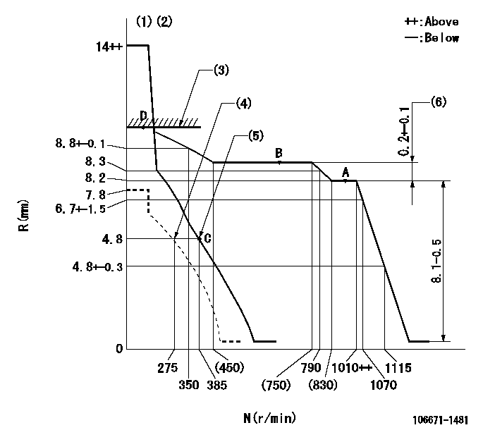
N:Pump speed
R:Rack position (mm)
(1)Notch fixed: K
(2)Tolerance for racks not indicated: +-0.05mm.
(3)RACK LIMIT
(4)Set idle sub-spring
(5)Main spring setting
(6)Rack difference between N = N1 and N = N2
----------
K=15 N1=1000r/min N2=700r/min
----------
----------
K=15 N1=1000r/min N2=700r/min
----------
Speed control lever angle

F:Full speed
I:Idle
(1)Stopper bolt setting
----------
----------
a=(6deg)+-5deg b=(19deg)+-5deg
----------
----------
a=(6deg)+-5deg b=(19deg)+-5deg
Stop lever angle
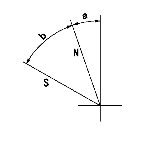
N:Pump normal
S:Stop the pump.
----------
----------
a=22deg+-5deg b=46deg+-5deg
----------
----------
a=22deg+-5deg b=46deg+-5deg
Timing setting

(1)Pump vertical direction
(2)Position of timer's threaded hole at No 1 cylinder's beginning of injection
(3)B.T.D.C.: aa
(4)-
----------
aa=16deg
----------
a=(70deg)
----------
aa=16deg
----------
a=(70deg)
Information:
START BY:a. remove valve coversb. remove fuel injection lines 1. Use tool (A) and a 5P328 crowfoot wrench (7/8") to loosen the fuel injection line nut at the nozzle end.
Do not let the tops of the fuel nozzles turn when the fuel lines are loosened. The nozzles will be damaged if the top of the nozzles turn in the body.
2. Use tool (B) to loosen the nut at the fuel injection line adapter end. Remove inner fuel injection lines (1). Install plugs in the fuel injection nozzles. 3. Remove the nut that holds the adapters to the cylinder head assembly. Remove fuel injection line adapters (2).Install Fuel Injection Line Adapters
1. Check the condition of O-ring seal (1) on fuel injection line adapter (2) for damage. Make a replacement if necessary.2. Lubricate O-ring seal (1) with clean engine oil. Install fuel injection line adapter (2). Tighten the retaining nut to a torque of 13.6 2.7 N m (10 2 lb.ft.). 3. Check the condition of the O-ring seal on inner fuel line (3) for damage, and make a replacement if necessary. Install inner fuel line (3).
Do not let the tops of the fuel nozzles turn when the fuel lines are tightened. The nozzles will be damaged if the top of the nozzles turn in the body.
4. Use tooling (A) to tighten the inner fuel line nuts to a torque of 40 7 N m (30 5 lb.ft.).END BY:a. install fuel injection linesb. install valve covers
Have questions with 106671-1481?
Group cross 106671-1481 ZEXEL
Isuzu
Isuzu
106671-1481
9 400 610 324
1156023201
INJECTION-PUMP ASSEMBLY
6RB1T
6RB1T