Information injection-pump assembly
ZEXEL
106671-1368
1066711368
ISUZU
1156021402
1156021402
Rating:
Cross reference number
ZEXEL
106671-1368
1066711368
ISUZU
1156021402
1156021402
Zexel num
Bosch num
Firm num
Name
Calibration Data:
Adjustment conditions
Test oil
1404 Test oil ISO4113 or {SAEJ967d}
1404 Test oil ISO4113 or {SAEJ967d}
Test oil temperature
degC
40
40
45
Nozzle and nozzle holder
105780-8140
Bosch type code
EF8511/9A
Nozzle
105780-0000
Bosch type code
DN12SD12T
Nozzle holder
105780-2080
Bosch type code
EF8511/9
Opening pressure
MPa
17.2
Opening pressure
kgf/cm2
175
Injection pipe
Outer diameter - inner diameter - length (mm) mm 8-3-600
Outer diameter - inner diameter - length (mm) mm 8-3-600
Overflow valve opening pressure
kPa
157
123
191
Overflow valve opening pressure
kgf/cm2
1.6
1.25
1.95
Tester oil delivery pressure
kPa
157
157
157
Tester oil delivery pressure
kgf/cm2
1.6
1.6
1.6
Direction of rotation (viewed from drive side)
Left L
Left L
Injection timing adjustment
Direction of rotation (viewed from drive side)
Left L
Left L
Injection order
1-5-3-6-
2-4
Pre-stroke
mm
3.7
3.67
3.73
Beginning of injection position
Governor side NO.1
Governor side NO.1
Difference between angles 1
Cal 1-5 deg. 60 59.75 60.25
Cal 1-5 deg. 60 59.75 60.25
Difference between angles 2
Cal 1-3 deg. 120 119.75 120.25
Cal 1-3 deg. 120 119.75 120.25
Difference between angles 3
Cal 1-6 deg. 180 179.75 180.25
Cal 1-6 deg. 180 179.75 180.25
Difference between angles 4
Cyl.1-2 deg. 240 239.75 240.25
Cyl.1-2 deg. 240 239.75 240.25
Difference between angles 5
Cal 1-4 deg. 300 299.75 300.25
Cal 1-4 deg. 300 299.75 300.25
Injection quantity adjustment
Adjusting point
A
Rack position
8.5
Pump speed
r/min
650
650
650
Average injection quantity
mm3/st.
131.5
129.5
133.5
Max. variation between cylinders
%
0
-3
3
Basic
*
Fixing the lever
*
Boost pressure
kPa
30.7
30.7
Boost pressure
mmHg
230
230
Injection quantity adjustment_02
Adjusting point
B
Rack position
7.7
Pump speed
r/min
1100
1100
1100
Average injection quantity
mm3/st.
119.8
117.8
121.8
Max. variation between cylinders
%
0
-4
4
Fixing the lever
*
Boost pressure
kPa
30.7
30.7
Boost pressure
mmHg
230
230
Injection quantity adjustment_03
Adjusting point
C
Rack position
5.4+-0.5
Pump speed
r/min
250
250
250
Average injection quantity
mm3/st.
8.2
5
11.4
Max. variation between cylinders
%
0
-13
13
Fixing the rack
*
Boost pressure
kPa
0
0
0
Boost pressure
mmHg
0
0
0
Injection quantity adjustment_04
Adjusting point
D
Rack position
-
Pump speed
r/min
150
150
150
Average injection quantity
mm3/st.
85
85
Fixing the lever
*
Boost pressure
kPa
0
0
0
Boost pressure
mmHg
0
0
0
Boost compensator adjustment
Pump speed
r/min
650
650
650
Rack position
7
Boost pressure
kPa
3.3
3.3
5.3
Boost pressure
mmHg
25
25
40
Boost compensator adjustment_02
Pump speed
r/min
650
650
650
Rack position
8.5
Boost pressure
kPa
17.3
17.3
17.3
Boost pressure
mmHg
130
130
130
Test data Ex:
Governor adjustment
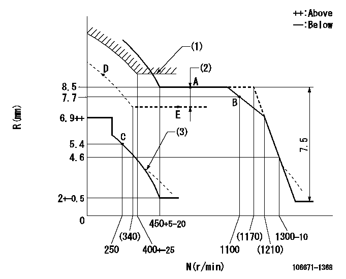
N:Pump speed
R:Rack position (mm)
(1)Excess fuel setting for starting: SXL
(2)Boost compensator stroke: BCL
(3)Damper spring setting: DL
----------
SXL=8.6+0.2mm BCL=1.5+-0.1mm DL=4.4-0.5mm
----------
----------
SXL=8.6+0.2mm BCL=1.5+-0.1mm DL=4.4-0.5mm
----------
Timer adjustment

(1)Adjusting range
(2)Step response time
(N): Speed of the pump
(L): Load
(theta) Advance angle
(Srd1) Step response time 1
(Srd2) Step response time 2
1. Adjusting conditions for the variable timer
(1)Adjust the clearance between the pickup and the protrusion to L.
----------
L=1-0.2mm N2=800r/min C2=(5.5)deg t1=2--sec. t2=2--sec.
----------
N1=800++r/min P1=0kPa(0kgf/cm2) P2=392kPa(4kgf/cm2) C1=5.5+-0.3deg R01=0/4load R02=4/4load
----------
L=1-0.2mm N2=800r/min C2=(5.5)deg t1=2--sec. t2=2--sec.
----------
N1=800++r/min P1=0kPa(0kgf/cm2) P2=392kPa(4kgf/cm2) C1=5.5+-0.3deg R01=0/4load R02=4/4load
Speed control lever angle

F:Full speed
----------
----------
a=8deg+-5deg
----------
----------
a=8deg+-5deg
0000000901

F:Full load
I:Idle
(1)Stopper bolt setting
(2)Use the hole at R = aa
----------
aa=35mm
----------
a=15deg+-5deg b=35deg+-3deg
----------
aa=35mm
----------
a=15deg+-5deg b=35deg+-3deg
Stop lever angle

N:Pump normal
S:Stop the pump.
----------
----------
a=37deg+-5deg b=73deg+-5deg
----------
----------
a=37deg+-5deg b=73deg+-5deg
0000001501 RACK SENSOR

V1:Supply voltage
V2f:Full side output voltage
V2i:Idle side output voltage
(A) Black
(B) Yellow
(C) Red
(D) Trimmer
(E): Shaft
(F) Nut
(G) Load lever
1. Load sensor adjustment
(1)Connect as shown in the above diagram and apply supply voltage V1.
(2)Hold the load lever (G) against the full side.
(3)Turn the shaft so that the voltage between (A) and (B) is V2.
(4)Hold the load lever (G) against the idle side.
(5)Adjust (D) so that the voltage between (A) and (B) is V2i.
(6)Repeat the above adjustments.
(7)Tighten the nut (F) at the point satisfying the standards.
(8)Hold the load lever against the full side stopper and the idle side stopper.
(9)At this time, confirm that the full side output voltage is V2f and the idle side output voltage is V2i.
----------
V1= 5+-0.02V V2f=0.15+0.03V V2i=2.35-0.03V
----------
----------
V1= 5+-0.02V V2f=0.15+0.03V V2i=2.35-0.03V
----------
Timing setting

(1)Pump vertical direction
(2)Position of timer's threaded hole at No 1 cylinder's beginning of injection
(3)-
(4)-
----------
----------
a=(40deg)
----------
----------
a=(40deg)
Information:
(Engine Crankshaft Turns Freely) (Exhaust Smoke Can Be Seen While Starting)
Recommended Procedure
1. Cold Outside Temperatures ... It may be necessary to use starting aids, or to heat engine oil or coolant at temperatures below 10°C (50°F).2. Air in Fuel System ... With air in the fuel system the engine will normally be difficult to start, run rough and release a large amount of white smoke. To remove the air from the fuel system, open the manual bleed valve on the fuel injection pump housing. Operate the priming pump until the flow of fuel from the manual bleed valve is free of air. Close the manual bleed valve and fasten the fuel priming pump. Start the engine. If the engine still does not run smooth or releases a large amount of white smoke, loosen the fuel line nuts one at a time at the cylinder heads, and permit the fuel to come out until it is free of air. Tighten the fuel line nuts. If air is not removed in this way, put 35 kPa (5 psi) of air pressure to the fuel tank.
Do not use more than 55 kPa (8 psi) of air pressure in the fuel tank or damage to the tank may result.
Check for leakage at the connections between the fuel tank and the fuel transfer pump. If leaks are found, tighten the connections or replace the lines. If there are no visual leaks, remove the fuel supply line from the tank and connect it to an outside fuel supply. If this corrects the problem, the suction line (standpipe) inside the fuel tank has a leak.3. Low Quality Fuel ... Remove a small amount of fuel from the tank and check for water in the fuel. If there is water in the fuel, remove fuel from the tank until it is free of water and fill with a good quality fuel. Change the fuel filter and "prime" (remove the air and/or low quality fuel from the fuel system) the fuel system with the fuel priming pump. If there is no water in the fuel, prime and start the engine by using an outside source of fuel. If engine starts correctly using different fuel, remove all fuel from the tank and fill with good quality fuel. Prime the fuel system if necessary.4. Low Fuel Pressure ... Change the fuel filter. If the pressure is still low, check the bypass valve in the fuel transfer pump. Debris in the system can make the valve become stationary in the open position.5. Fuel Injection Timing Not Correct ... Check and make necessary adjustments as per Testing and Adjusting section of this Service Manual.6. Valve Adjustment Not Correct ... Check and make necessary adjustments as per Testing and Adjusting section of this Service Manual. Intake valve clearance is 0.38 mm (.015 in) and exhaust valve clearance is 0.64 mm (.025 in).7. Bad Fuel Nozzle(s) ... Remove and test the fuel nozzles.8. Low Compression ... See Misfiring and Running Rough.Exhaust Smoke