Information injection-pump assembly
ZEXEL
106671-1291
1066711291
ISUZU
1156011921
1156011921
Rating:
Cross reference number
ZEXEL
106671-1291
1066711291
ISUZU
1156011921
1156011921
Zexel num
Bosch num
Firm num
Name
Calibration Data:
Adjustment conditions
Test oil
1404 Test oil ISO4113 or {SAEJ967d}
1404 Test oil ISO4113 or {SAEJ967d}
Test oil temperature
degC
40
40
45
Nozzle and nozzle holder
105780-8140
Bosch type code
EF8511/9A
Nozzle
105780-0000
Bosch type code
DN12SD12T
Nozzle holder
105780-2080
Bosch type code
EF8511/9
Opening pressure
MPa
17.2
Opening pressure
kgf/cm2
175
Injection pipe
Outer diameter - inner diameter - length (mm) mm 8-3-600
Outer diameter - inner diameter - length (mm) mm 8-3-600
Overflow valve opening pressure
kPa
157
123
191
Overflow valve opening pressure
kgf/cm2
1.6
1.25
1.95
Tester oil delivery pressure
kPa
157
157
157
Tester oil delivery pressure
kgf/cm2
1.6
1.6
1.6
Direction of rotation (viewed from drive side)
Left L
Left L
Injection timing adjustment
Direction of rotation (viewed from drive side)
Left L
Left L
Injection order
1-5-3-6-
2-4
Pre-stroke
mm
4.2
4.15
4.25
Beginning of injection position
Governor side NO.1
Governor side NO.1
Difference between angles 1
Cal 1-5 deg. 60 59.5 60.5
Cal 1-5 deg. 60 59.5 60.5
Difference between angles 2
Cal 1-3 deg. 120 119.5 120.5
Cal 1-3 deg. 120 119.5 120.5
Difference between angles 3
Cal 1-6 deg. 180 179.5 180.5
Cal 1-6 deg. 180 179.5 180.5
Difference between angles 4
Cyl.1-2 deg. 240 239.5 240.5
Cyl.1-2 deg. 240 239.5 240.5
Difference between angles 5
Cal 1-4 deg. 300 299.5 300.5
Cal 1-4 deg. 300 299.5 300.5
Injection quantity adjustment
Adjusting point
A
Rack position
10.3
Pump speed
r/min
1150
1150
1150
Average injection quantity
mm3/st.
128.5
126.9
130.1
Max. variation between cylinders
%
0
-2.5
2.5
Basic
*
Fixing the lever
*
Boost pressure
kPa
60
60
Boost pressure
mmHg
450
450
Injection quantity adjustment_02
Adjusting point
B
Rack position
6.1+-0.5
Pump speed
r/min
265
265
265
Average injection quantity
mm3/st.
13
11
15
Max. variation between cylinders
%
0
-14
14
Fixing the rack
*
Boost pressure
kPa
0
0
0
Boost pressure
mmHg
0
0
0
Boost compensator adjustment
Pump speed
r/min
550
550
550
Rack position
8.9
Boost pressure
kPa
13.3
12
14.6
Boost pressure
mmHg
100
90
110
Boost compensator adjustment_02
Pump speed
r/min
550
550
550
Rack position
10.3
Boost pressure
kPa
46.7
40
53.4
Boost pressure
mmHg
350
300
400
Timer adjustment
Pump speed
r/min
1050--
Advance angle
deg.
0
0
0
Remarks
Start
Start
Timer adjustment_02
Pump speed
r/min
1000
Advance angle
deg.
0.5
Timer adjustment_03
Pump speed
r/min
1150
Advance angle
deg.
1.6
1.1
2.1
Timer adjustment_04
Pump speed
r/min
-
Advance angle
deg.
3
3
3
Remarks
Measure the actual speed, stop
Measure the actual speed, stop
Test data Ex:
Governor adjustment
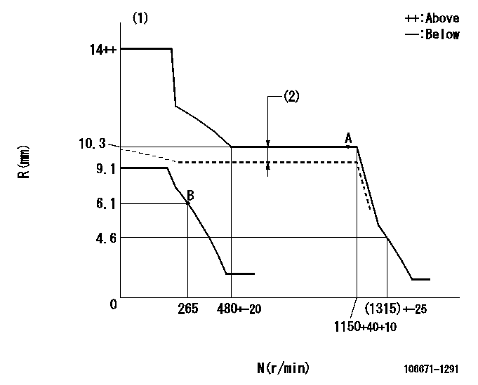
N:Pump speed
R:Rack position (mm)
(1)Notch fixed: K
(2)Boost compensator stroke: BCL
----------
K=6 BCL=1.4+-0.1mm
----------
----------
K=6 BCL=1.4+-0.1mm
----------
Speed control lever angle
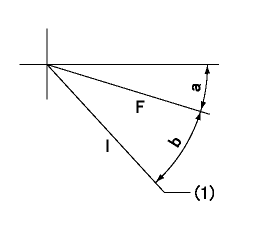
F:Full speed
I:Idle
(1)Stopper bolt setting
----------
----------
a=7deg+-5deg b=25deg+-5deg
----------
----------
a=7deg+-5deg b=25deg+-5deg
Stop lever angle

N:Pump normal
S:Stop the pump.
----------
----------
a=19deg+-5deg b=53deg+-5deg
----------
----------
a=19deg+-5deg b=53deg+-5deg
Timing setting

(1)Pump vertical direction
(2)Positions of coupling's threaded installation holes at No 1 cylinder's beginning of injection
(3)B.T.D.C.: aa
(4)-
----------
aa=11deg
----------
a=(40deg)
----------
aa=11deg
----------
a=(40deg)
Information:
preparatory steps: a) remove flywheel housingb) remove timing gear coverc) remove pistons1. Lay the engine on its side or top in a suitable stand.2. Attach a hoist to the crankshaft. 3. Remove the main bearing caps (1). 4. Remove the crankshaft-weight 200 lbs. (91 kg).5. Remove the crankshaft main bearings from the cylinder block and main bearing caps.
If the main bearings are not going to be replaced mark them with respect to their location in the engine.
6. Using tool setup (A), remove the crankshaft gear and oil seal wear sleeve.Install Crankshaft
1. Heat the crankshaft gear and the oil seal wear sleeve, maximum 600°F (316°C), and install them on the crankshaft.2. Clean the bearing seating surfaces in the cylinder block and the main bearing caps. Install the upper and lower halves of the bearings in the cylinder block bearing caps. Lubricate the bearings with clean SAE 30 engine oil.
If the main bearings are not being replaced the original bearings must be installed in the same location they were removed from.
3. Attach a hoist and position the crankshaft in the cylinder block with the timing marks (1) aligned. 4. Using wire (A), check the main bearing clearance. Install the caps in the respective positions with the number stamped on cap facing the corresponding number cast on side of the cylinder block web. 5. Lubricate the threads of bearing cap retaining bolts and face of washers with clean SAE 30 engine oil. Install the retaining bolts and washers. Tighten both bolts to 30 3 lb. ft. (4,1 0,4 mkg). Mark both bolt heads and bearing caps then tighten each bolt an additional 90° from mark. Remove bearing caps and measure thickness of wire (A). Main bearing clearance should be .0030-.0059 in. (0,076-0,150 mm).6. Lubricate the lower halves of main bearings with clean SAE 30 engine oil. Install main bearing caps in their respective positions. Install cap retaining bolts and washers. Tighten both bolts to 30 3 lb. ft. (4,1 0,4 mkg). Mark both bolt heads and bearing caps then tighten each bolt an additional 90° from mark. 7. Using tool setup (B), check the crankshaft end play as controlled by thrust bearing (2) on rear main bearing. End play should be .0025-.0145 in. (0,064-0,368 mm). Maximum permissible end play is .025 in. (0,64 mm).concluding steps: a) install pistonsb) install timing gear coverc) install flywheel housingd) check fuel injection pump timing. See REMOVE AND INSTALL FUEL INJECTION PUMP HOUSING AND GOVERNOR AS A UNIT.