Information injection-pump assembly
ZEXEL
106671-0970
1066710970

Rating:
Service parts 106671-0970 INJECTION-PUMP ASSEMBLY:
1.
_
7.
COUPLING PLATE
8.
_
9.
_
11.
Nozzle and Holder
16600-96571
12.
Open Pre:MPa(Kqf/cm2)
17.7{180}/22.6{230}
15.
NOZZLE SET
Include in #1:
106671-0970
as INJECTION-PUMP ASSEMBLY
Cross reference number
ZEXEL
106671-0970
1066710970
Zexel num
Bosch num
Firm num
Name
Calibration Data:
Adjustment conditions
Test oil
1404 Test oil ISO4113 or {SAEJ967d}
1404 Test oil ISO4113 or {SAEJ967d}
Test oil temperature
degC
40
40
45
Nozzle and nozzle holder
105780-8140
Bosch type code
EF8511/9A
Nozzle
105780-0000
Bosch type code
DN12SD12T
Nozzle holder
105780-2080
Bosch type code
EF8511/9
Opening pressure
MPa
17.2
Opening pressure
kgf/cm2
175
Injection pipe
Outer diameter - inner diameter - length (mm) mm 8-3-600
Outer diameter - inner diameter - length (mm) mm 8-3-600
Overflow valve
132424-0620
Overflow valve opening pressure
kPa
157
123
191
Overflow valve opening pressure
kgf/cm2
1.6
1.25
1.95
Tester oil delivery pressure
kPa
157
157
157
Tester oil delivery pressure
kgf/cm2
1.6
1.6
1.6
Direction of rotation (viewed from drive side)
Right R
Right R
Injection timing adjustment
Direction of rotation (viewed from drive side)
Right R
Right R
Injection order
1-4-2-6-
3-5
Pre-stroke
mm
3.9
3.85
3.95
Beginning of injection position
Drive side NO.1
Drive side NO.1
Difference between angles 1
Cal 1-4 deg. 60 59.5 60.5
Cal 1-4 deg. 60 59.5 60.5
Difference between angles 2
Cyl.1-2 deg. 120 119.5 120.5
Cyl.1-2 deg. 120 119.5 120.5
Difference between angles 3
Cal 1-6 deg. 180 179.5 180.5
Cal 1-6 deg. 180 179.5 180.5
Difference between angles 4
Cal 1-3 deg. 240 239.5 240.5
Cal 1-3 deg. 240 239.5 240.5
Difference between angles 5
Cal 1-5 deg. 300 299.5 300.5
Cal 1-5 deg. 300 299.5 300.5
Injection quantity adjustment
Adjusting point
A
Rack position
11.7
Pump speed
r/min
600
600
600
Average injection quantity
mm3/st.
188
186
190
Max. variation between cylinders
%
0
-4
4
Basic
*
Fixing the lever
*
Solenoid boost comp. OFF
*
Injection quantity adjustment_02
Adjusting point
C
Rack position
7+-0.5
Pump speed
r/min
225
225
225
Average injection quantity
mm3/st.
10
9
11
Max. variation between cylinders
%
0
-10
10
Fixing the rack
*
Solenoid boost comp. OFF
*
Injection quantity adjustment_03
Adjusting point
D
Rack position
9.35
Pump speed
r/min
300
300
300
Average injection quantity
mm3/st.
123.4
121.4
125.4
Fixing the lever
*
Solenoid boost comp. ON
*
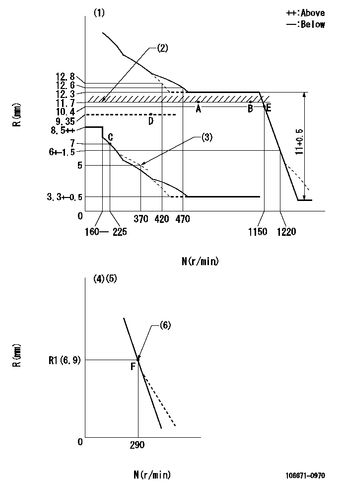
Test data Ex:
Governor adjustment

N:Pump speed
R:Rack position (mm)
(1)Tolerance for racks not indicated: +-0.05mm.
(2)Rack limit using stop lever
(3)Damper spring setting
(4)Variable speed specification: idling adjustment
(5)(Fix in the full position at delivery.)
(6)Main spring setting
----------
----------
----------
----------
Timer adjustment

(1)Adjusting range
(2)Step response time
(N): Speed of the pump
(L): Load
(theta) Advance angle
(Srd1) Step response time 1
(Srd2) Step response time 2
1. Adjusting conditions for the variable timer
(1)Adjust the clearance between the pickup and the protrusion to L.
----------
L=1-0.2mm N4=800r/min C4=(5.5deg) t1=2--sec. t2=2--sec.
----------
N1=300r/min N2=900++r/min N3=1100r/min C1=5.5+-0.3deg C2=3++deg C3=4--deg P1=0kPa(0kgf/cm2) P2=196kPa(2kgf/cm2) P3=392kPa(4kgf/cm2) R01=0/4load R02=4/4load R03=4/4load
----------
L=1-0.2mm N4=800r/min C4=(5.5deg) t1=2--sec. t2=2--sec.
----------
N1=300r/min N2=900++r/min N3=1100r/min C1=5.5+-0.3deg C2=3++deg C3=4--deg P1=0kPa(0kgf/cm2) P2=196kPa(2kgf/cm2) P3=392kPa(4kgf/cm2) R01=0/4load R02=4/4load R03=4/4load
Speed control lever angle

F:Full speed
I:Idle
(1)(Pump speed = aa)
(2)Set the stopper bolt (fixed at full-load position at delivery.)
----------
aa=290r/min
----------
a=(13deg)+-5deg b=5.5deg+-5deg
----------
aa=290r/min
----------
a=(13deg)+-5deg b=5.5deg+-5deg
0000000901

F:Full load
I:Idle
(1)Stopper bolt setting
----------
----------
a=33.5deg+-3deg b=45deg+-5deg
----------
----------
a=33.5deg+-3deg b=45deg+-5deg
Stop lever angle

N:Pump normal
S:Stop the pump.
(1)Rack position = aa
----------
aa=11.7mm
----------
a=34.5deg+-5deg b=34.5deg+-5deg
----------
aa=11.7mm
----------
a=34.5deg+-5deg b=34.5deg+-5deg
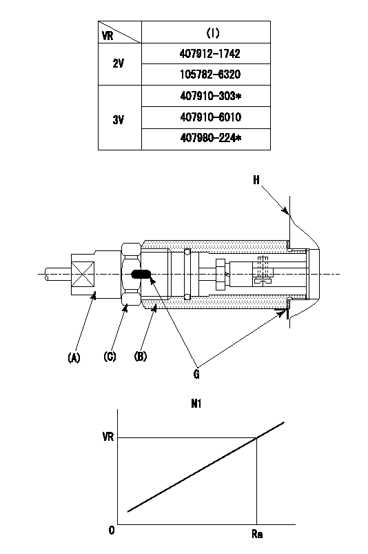
0000001501 RACK SENSOR

(VR) measurement voltage
(I) Part number of the control unit
(G) Apply red paint.
(H): End surface of the pump
1. Rack sensor adjustment (-0620)
(1)Fix the speed control lever at the full position
(2)Set the speed to N1 r/min.
(If the boost compensator is provided, apply boost pressure.)
(3)Adjust the bobbin (A) so that the rack sensor's output voltage is VR+-0.01.
(4)At that time, rack position must be Ra.
(5)Apply G at two places.
Connecting part between the joint (B) and the nut (F)
Connecting part between the joint (B) and the end surface of the pump (H)
----------
N1=600r/min Ra=11.7mm
----------
----------
N1=600r/min Ra=11.7mm
----------
0000001601 BCS

(A) Screw for precise adjustment
(B) Pre-adjustment screw
(C) Control rack, rack decrease direction
(D) Rack limit
1. Solenoid boost compensator adjustment
(1)Supply DC: V1 to the solenoid terminals and confirm solenoid operation.
(2)With the solenoid ON, calculate L1 from the value of R1. [L1 = La - (10.5 - R1) +-0.2]
(3)Adjust (B) to obtain L1.
(4)Assemble the solenoid to the governor.
(5)With the solenoid ON, readjust (B) so that R1 is within the allowance a.
(6)With the solenoid OFF, perform all governor adjustments except rack limit adjustment.
(7)Set the pump speed at N1 and turn the solenoid ON.
(8)Adjust (A) so that R1 is within the allowance range a.
(9)Set the pump speed at N1 and fix the load lever in the full position
(10)Turn the solenoid switch ON and OFF several times and confirm that the difference in rack positions is within L2.
(11)Set the rack limit.
(12)Stamp the solenoid valve.
----------
V1=24V N1=300r/min N2=0r/min R1=R2(9.35)mm a=+-0.5mm L1=26.85+-0.2mm L2=3.5~5mm La=28mm
----------
----------
V1=24V N1=300r/min N2=0r/min R1=R2(9.35)mm a=+-0.5mm L1=26.85+-0.2mm L2=3.5~5mm La=28mm
----------
Timing setting

(1)Pump vertical direction
(2)Coupling's key groove position at No 1 cylinder's beginning of injection
(3)-
(4)-
----------
----------
a=(30deg)
----------
----------
a=(30deg)
Information:
Lubrication System
The lubrication system consists of the oil pump, cooler, filters, internal passages and the oil pan. The pan can be turned end-for-end to provide either a front or rear sump. The dipstick placement and suction tube length correspond with sump location. A longer suction tube and support is required when the pan is positioned for a rear sump.Oil moves through the screen and suction tube to the inlet passage in the oil pump cover. The oil pump cover bolts to the back of the engine front cover. The inlet passage directs oil to the pump.The oil pump is a six lobe, rotor type. The crankshaft gear drives the outer rotor which rotates in a bearing in the front cover. The inner rotor mounts on a stub shaft in the front cover and is driven by the outer rotor.A bypass valve in the pump cover senses pump outlet pressure. The valve opens at approximately 72 psi (5.1 kg/cm2) and bypasses oil back to the inlet side of the pump.Oil from the pump flows through a passage in the front cover to the cylinder block and on to the oil cooler base. The base mounts on the left side of the block. A valve in the base bypasses oil around the cooler when the oil is cold or the oil cooler restriction is higher than the rest of the system. A 14 to 22 psi (0.89 to 1.55 kg/cm2) pressure differential opens the valve.Oil from the cooler flows to two spin on, throw away filters mounted on the oil cooler base. Each filter contains a bypass valve. If the filters become clogged, oil is bypassed around them. An 18 to 20 psi (1.27 to 1.41 kg/cm2) pressure differential opens the valves.There are three pressure taps in the oil cooler base. Two taps, located on the outlet side of the cooler and filters, are for the oil pressure gauge and a low pressure alarm. One, located on the bypass spring retainer, provides supply oil for an auxiliary filter.A drilled passage in the block directs oil from the filters to the oil manifold. The oil manifold is in the vee above the camshaft mounting and extends the length of the block. Oil flows from the manifold to the camshaft bearings. There are grooves in the cylinder block bore around the camshaft bearings. The camshaft journals are lubricated from these grooves through a hole in the bearing. The remaining oil flows around the groove and down through a drilled passage to a hole and a groove in the upper half of the main bearings. Oil from the hole and groove lubricates the main bearing journals.Oil flows into the crankshaft through holes in the main bearing journals. Drilled passages connect each main bearing journal with the adjacent connecting rod journals. The piston pins are splash lubricated.The rocker arms receive oil from the oil manifold. Drilled passages in the block align with a passage in each of the cylinder heads. The passage to the
The lubrication system consists of the oil pump, cooler, filters, internal passages and the oil pan. The pan can be turned end-for-end to provide either a front or rear sump. The dipstick placement and suction tube length correspond with sump location. A longer suction tube and support is required when the pan is positioned for a rear sump.Oil moves through the screen and suction tube to the inlet passage in the oil pump cover. The oil pump cover bolts to the back of the engine front cover. The inlet passage directs oil to the pump.The oil pump is a six lobe, rotor type. The crankshaft gear drives the outer rotor which rotates in a bearing in the front cover. The inner rotor mounts on a stub shaft in the front cover and is driven by the outer rotor.A bypass valve in the pump cover senses pump outlet pressure. The valve opens at approximately 72 psi (5.1 kg/cm2) and bypasses oil back to the inlet side of the pump.Oil from the pump flows through a passage in the front cover to the cylinder block and on to the oil cooler base. The base mounts on the left side of the block. A valve in the base bypasses oil around the cooler when the oil is cold or the oil cooler restriction is higher than the rest of the system. A 14 to 22 psi (0.89 to 1.55 kg/cm2) pressure differential opens the valve.Oil from the cooler flows to two spin on, throw away filters mounted on the oil cooler base. Each filter contains a bypass valve. If the filters become clogged, oil is bypassed around them. An 18 to 20 psi (1.27 to 1.41 kg/cm2) pressure differential opens the valves.There are three pressure taps in the oil cooler base. Two taps, located on the outlet side of the cooler and filters, are for the oil pressure gauge and a low pressure alarm. One, located on the bypass spring retainer, provides supply oil for an auxiliary filter.A drilled passage in the block directs oil from the filters to the oil manifold. The oil manifold is in the vee above the camshaft mounting and extends the length of the block. Oil flows from the manifold to the camshaft bearings. There are grooves in the cylinder block bore around the camshaft bearings. The camshaft journals are lubricated from these grooves through a hole in the bearing. The remaining oil flows around the groove and down through a drilled passage to a hole and a groove in the upper half of the main bearings. Oil from the hole and groove lubricates the main bearing journals.Oil flows into the crankshaft through holes in the main bearing journals. Drilled passages connect each main bearing journal with the adjacent connecting rod journals. The piston pins are splash lubricated.The rocker arms receive oil from the oil manifold. Drilled passages in the block align with a passage in each of the cylinder heads. The passage to the
