Information injection-pump assembly
ZEXEL
106671-0610
1066710610
Rating:
Cross reference number
ZEXEL
106671-0610
1066710610
Zexel num
Bosch num
Firm num
Name
Calibration Data:
Adjustment conditions
Test oil
1404 Test oil ISO4113 or {SAEJ967d}
1404 Test oil ISO4113 or {SAEJ967d}
Test oil temperature
degC
40
40
45
Nozzle and nozzle holder
105780-8140
Bosch type code
EF8511/9A
Nozzle
105780-0000
Bosch type code
DN12SD12T
Nozzle holder
105780-2080
Bosch type code
EF8511/9
Opening pressure
MPa
17.2
Opening pressure
kgf/cm2
175
Injection pipe
Outer diameter - inner diameter - length (mm) mm 8-3-600
Outer diameter - inner diameter - length (mm) mm 8-3-600
Overflow valve opening pressure
kPa
157
123
191
Overflow valve opening pressure
kgf/cm2
1.6
1.25
1.95
Tester oil delivery pressure
kPa
157
157
157
Tester oil delivery pressure
kgf/cm2
1.6
1.6
1.6
Direction of rotation (viewed from drive side)
Right R
Right R
Injection timing adjustment
Direction of rotation (viewed from drive side)
Right R
Right R
Injection order
1-4-2-6-
3-5
Pre-stroke
mm
3.65
3.6
3.7
Beginning of injection position
Drive side NO.1
Drive side NO.1
Difference between angles 1
Cal 1-4 deg. 60 59.5 60.5
Cal 1-4 deg. 60 59.5 60.5
Difference between angles 2
Cyl.1-2 deg. 120 119.5 120.5
Cyl.1-2 deg. 120 119.5 120.5
Difference between angles 3
Cal 1-6 deg. 180 179.5 180.5
Cal 1-6 deg. 180 179.5 180.5
Difference between angles 4
Cal 1-3 deg. 240 239.5 240.5
Cal 1-3 deg. 240 239.5 240.5
Difference between angles 5
Cal 1-5 deg. 300 299.5 300.5
Cal 1-5 deg. 300 299.5 300.5
Injection quantity adjustment
Adjusting point
A
Rack position
13
Pump speed
r/min
600
600
600
Average injection quantity
mm3/st.
183.9
181.9
185.9
Max. variation between cylinders
%
0
-4
4
Basic
*
Fixing the lever
*
Boost pressure
kPa
56
56
Boost pressure
mmHg
420
420
Injection quantity adjustment_02
Adjusting point
B
Rack position
12.3
Pump speed
r/min
1050
1050
1050
Average injection quantity
mm3/st.
169.8
166.8
172.8
Max. variation between cylinders
%
0
-5
5
Fixing the lever
*
Boost pressure
kPa
56
56
Boost pressure
mmHg
420
420
Injection quantity adjustment_03
Adjusting point
C
Rack position
12.8+-0.
5
Pump speed
r/min
850
850
850
Average injection quantity
mm3/st.
179.8
171.8
187.8
Fixing the lever
*
Boost pressure
kPa
56
56
Boost pressure
mmHg
420
420
Injection quantity adjustment_04
Adjusting point
D
Rack position
7.8+-0.5
Pump speed
r/min
225
225
225
Average injection quantity
mm3/st.
12
11
13
Max. variation between cylinders
%
0
-10
10
Fixing the rack
*
Boost pressure
kPa
0
0
0
Boost pressure
mmHg
0
0
0
Injection quantity adjustment_05
Adjusting point
E
Rack position
R1(10.9)
Pump speed
r/min
300
300
300
Average injection quantity
mm3/st.
123.4
121.4
125.4
Fixing the lever
*
Boost pressure
kPa
0
0
0
Boost pressure
mmHg
0
0
0
Boost compensator adjustment
Pump speed
r/min
300
300
300
Rack position
R1(10.9)
Boost pressure
kPa
8.7
8
9.4
Boost pressure
mmHg
65
60
70
Boost compensator adjustment_02
Pump speed
r/min
300
300
300
Rack position
R1(10.9)
+1.3
Boost pressure
kPa
28.7
28.7
28.7
Boost pressure
mmHg
215
215
215
Boost compensator adjustment_03
Pump speed
r/min
300
300
300
Rack position
13+0.2
Boost pressure
kPa
42.7
42.7
42.7
Boost pressure
mmHg
320
320
320
Test data Ex:
Governor adjustment
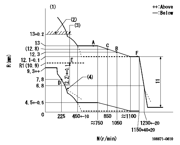
N:Pump speed
R:Rack position (mm)
(1)Perform governor adjustment at an ambient temperature of at least 15 deg C (boost compensator start spring is shape memory alloy).
(2)Rack limit using stop lever
(3)Boost compensator stroke (at N = N1)
(4)Damper spring setting: DL
----------
N1=300r/min DL=6.8-0.2mm
----------
----------
N1=300r/min DL=6.8-0.2mm
----------
Timer adjustment

(1)Adjusting range
(2)Step response time
(N): Speed of the pump
(L): Load
(theta) Advance angle
(Srd1) Step response time 1
(Srd2) Step response time 2
1. Adjusting conditions for the variable timer
(1)Adjust the clearance between the pickup and the protrusion to L.
----------
L=1-0.2mm N4=800r/min C4=(7)deg t1=2--sec. t2=2--sec.
----------
N1=300r/min N2=900++r/min N3=1100r/min C1=7+-0.3deg C2=3++deg C3=4--deg P1=0kPa(0kgf/cm2) P2=196kPa(2kgf/cm2) P3=392kPa(4kgf/cm2) R01=0/4load R02=4/4load R03=4/4load
----------
L=1-0.2mm N4=800r/min C4=(7)deg t1=2--sec. t2=2--sec.
----------
N1=300r/min N2=900++r/min N3=1100r/min C1=7+-0.3deg C2=3++deg C3=4--deg P1=0kPa(0kgf/cm2) P2=196kPa(2kgf/cm2) P3=392kPa(4kgf/cm2) R01=0/4load R02=4/4load R03=4/4load
Speed control lever angle

F:Full speed
----------
----------
a=32deg+-5deg
----------
----------
a=32deg+-5deg
0000000901
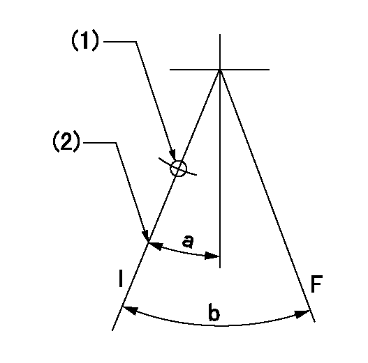
F:Full load
I:Idle
(1)At threaded hole above R = aa
(2)Stopper bolt setting
----------
aa=17mm
----------
a=22deg+-5deg b=31.5deg+-3deg
----------
aa=17mm
----------
a=22deg+-5deg b=31.5deg+-3deg
Stop lever angle
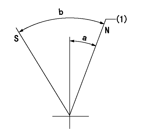
N:Pump normal
S:Stop the pump.
(1)Rack position = aa
----------
aa=13+0.2mm
----------
a=14.5deg+-5deg b=39deg+-5deg
----------
aa=13+0.2mm
----------
a=14.5deg+-5deg b=39deg+-5deg
0000001501 RACK SENSOR

(VR) measurement voltage
(I) Part number of the control unit
(G) Apply red paint.
(H): End surface of the pump
1. Rack sensor adjustment (-0620)
(1)Fix the speed control lever at the full position
(2)Set the speed to N1 r/min.
(If the boost compensator is provided, apply boost pressure.)
(3)Adjust the bobbin (A) so that the rack sensor's output voltage is VR+-0.01.
(4)At that time, rack position must be Ra.
(5)Apply G at two places.
Connecting part between the joint (B) and the nut (F)
Connecting part between the joint (B) and the end surface of the pump (H)
----------
N1=600r/min Ra=13mm
----------
----------
N1=600r/min Ra=13mm
----------
Timing setting

(1)Pump vertical direction
(2)Coupling's key groove position at No 1 cylinder's beginning of injection
(3)-
(4)-
----------
----------
a=(30deg)
----------
----------
a=(30deg)
Information:
3. Remove the water temperature regulator bypass water line (1).4. Disconnect the water inlet line from the bottom of the water pump. Disconnect the linkage for the governor.5. Disconnect the water supply line for the aftercooler.6. Install a 3/8"-16 NC forged eyebolt in the top of the water pump. Fasten a hoist to the water pump (2). Remove the bolts that hold the water pump to the engine and the engine oil cooler. Remove the water pump. Weight of the pump is 70 lb. (32 kg).Install Water Pump
1. Fasten a hoist to the water pump (1). Put the pump in position on the engine.2. Install the bolts that hold the water pump to the engine. Install the bolts (2) that fasten the water pump to the oil cooler.3. Install the water lines to the aftercooler and water temperature regulator housing.4. Install and adjust the drive belts on the water pump drive pulley. See LUBRICATION AND MAINTENANCE GUIDE.5. Fill the engine with oil and coolant to the correct levels.Disassemble Water
start by:a) remove water pump 1. Remove the pulley retaining nut and lock. Install tool (A) and remove the pulley. Remove the key.2. Remove the retainer and seal. Remove seal from retainer.3. Remove the cover retaining bolts and nuts. Remove the cover from the water pump housing. 4. Remove the impeller retaining nut. Remove the impeller (1) as the shaft is held and the impeller is turned clockwise.5. Remove the shaft assembly (2) from the housing. Remove the bearing assemblies and spacer from the shaft.6. Remove the carbon seal assembly and lip type seal from the housing.Assemble Water Pump
1. Use tool (A) to install the carbon seal assembly into water pump housing. Install the lip type seal in housing with lip of seal toward bearing assemblies. Put lubrication on the lip of seal with lubricant to be sealed.2. Install the bearing assemblies and spacer on the shaft. Install the shaft assembly in housing.3. Install the seal in the cage with lip of seal toward bearing assemblies. Put lubrication the lip of seal. Install the cage on the housing. 4. Install the pulley, lock and retaining nut. Tighten nut (2) to 100 10 lb.ft. (135.6 13.6 N m) and bend the lock.5. Install the impeller on shaft. Adjust impeller clearance (3) to .010 .005 in. (0.25 0.13 mm). Install the impeller retaining nut (1) and tighten to 50-55 lb. ft. (67.8-76.4 N m). After nut is tightened, hit the pulley end of shaft and check impeller clearance while impeller is turned.6. Install the water pump cover, retaining bolts and nuts.end by:a) install water pump