Information injection-pump assembly
BOSCH
9 400 613 475
9400613475
ZEXEL
106671-0596
1066710596
NISSAN-DIESEL
1671396774
1671396774
Rating:
Service parts 106671-0596 INJECTION-PUMP ASSEMBLY:
1.
_
7.
COUPLING PLATE
8.
_
9.
_
11.
Nozzle and Holder
1660096520
12.
Open Pre:MPa(Kqf/cm2)
22.6{230}

15.
NOZZLE SET
Include in #1:
106671-0596
as INJECTION-PUMP ASSEMBLY
Cross reference number
BOSCH
9 400 613 475
9400613475
ZEXEL
106671-0596
1066710596
NISSAN-DIESEL
1671396774
1671396774
Zexel num
Bosch num
Firm num
Name
106671-0596
9 400 613 475
1671396774 NISSAN-DIESEL
INJECTION-PUMP ASSEMBLY
PE6T K 14CA INJECTION PUMP ASSY PE6P,6PD PE
PE6T K 14CA INJECTION PUMP ASSY PE6P,6PD PE
Calibration Data:
Adjustment conditions
Test oil
1404 Test oil ISO4113 or {SAEJ967d}
1404 Test oil ISO4113 or {SAEJ967d}
Test oil temperature
degC
40
40
45
Nozzle and nozzle holder
105780-8140
Bosch type code
EF8511/9A
Nozzle
105780-0000
Bosch type code
DN12SD12T
Nozzle holder
105780-2080
Bosch type code
EF8511/9
Opening pressure
MPa
17.2
Opening pressure
kgf/cm2
175
Injection pipe
Outer diameter - inner diameter - length (mm) mm 8-3-600
Outer diameter - inner diameter - length (mm) mm 8-3-600
Overflow valve
132424-0620
Overflow valve opening pressure
kPa
157
123
191
Overflow valve opening pressure
kgf/cm2
1.6
1.25
1.95
Tester oil delivery pressure
kPa
157
157
157
Tester oil delivery pressure
kgf/cm2
1.6
1.6
1.6
Direction of rotation (viewed from drive side)
Right R
Right R
Injection timing adjustment
Direction of rotation (viewed from drive side)
Right R
Right R
Injection order
1-4-2-6-
3-5
Pre-stroke
mm
3.65
3.6
3.7
Beginning of injection position
Drive side NO.1
Drive side NO.1
Difference between angles 1
Cal 1-4 deg. 60 59.5 60.5
Cal 1-4 deg. 60 59.5 60.5
Difference between angles 2
Cyl.1-2 deg. 120 119.5 120.5
Cyl.1-2 deg. 120 119.5 120.5
Difference between angles 3
Cal 1-6 deg. 180 179.5 180.5
Cal 1-6 deg. 180 179.5 180.5
Difference between angles 4
Cal 1-3 deg. 240 239.5 240.5
Cal 1-3 deg. 240 239.5 240.5
Difference between angles 5
Cal 1-5 deg. 300 299.5 300.5
Cal 1-5 deg. 300 299.5 300.5
Injection quantity adjustment
Adjusting point
A
Rack position
11.6
Pump speed
r/min
600
600
600
Average injection quantity
mm3/st.
154.8
152.8
156.8
Max. variation between cylinders
%
0
-4
4
Basic
*
Fixing the lever
*
Boost pressure
kPa
29.3
29.3
Boost pressure
mmHg
220
220
Injection quantity adjustment_02
Adjusting point
C
Rack position
10.4
Pump speed
r/min
300
300
300
Average injection quantity
mm3/st.
117.4
115.4
119.4
Fixing the lever
*
Boost pressure
kPa
0
0
0
Boost pressure
mmHg
0
0
0
Injection quantity adjustment_03
Adjusting point
E
Rack position
8.1+-0.5
Pump speed
r/min
250
250
250
Average injection quantity
mm3/st.
15
14
16
Max. variation between cylinders
%
0
-10
10
Fixing the rack
*
Boost pressure
kPa
0
0
0
Boost pressure
mmHg
0
0
0
Boost compensator adjustment
Pump speed
r/min
300
300
300
Rack position
10.4
Boost pressure
kPa
4
2.7
5.3
Boost pressure
mmHg
30
20
40
Boost compensator adjustment_02
Pump speed
r/min
300
300
300
Rack position
12.3+0.2
Boost pressure
kPa
16
16
16
Boost pressure
mmHg
120
120
120
Timer adjustment
Pump speed
r/min
1150++
Advance angle
deg.
0
0
0
Remarks
Do not advance until starting N = 1150.
Do not advance until starting N = 1150.
Timer adjustment_02
Pump speed
r/min
-
Advance angle
deg.
2
2
2
Remarks
Measure the actual speed, stop
Measure the actual speed, stop
Test data Ex:
Governor adjustment
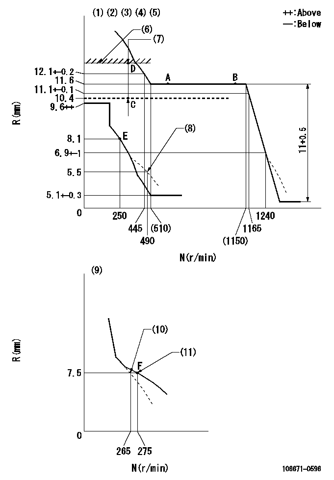
N:Pump speed
R:Rack position (mm)
(1)Maximum - minimum speed specification (using speed lever at adjustment)
(2)Lever ratio: RT
(3)Target shim dimension: TH
(4)Tolerance for racks not indicated: +-0.05mm.
(5)Perform governor adjustment at an ambient temperature of at least 15 deg C (boost compensator start spring is shape memory alloy).
(6)Rack limit using the stop lever: R1
(7)Boost compensator stroke: BCL
(8)Damper spring setting
(9)Variable speed specification: idling adjustment
(10)Main spring setting
(11)Set idle sub-spring
----------
RT=1 TH=1.9mm R1=12.3+0.2mm BCL=2+-0.1mm
----------
----------
RT=1 TH=1.9mm R1=12.3+0.2mm BCL=2+-0.1mm
----------
Speed control lever angle
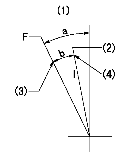
F:Full speed
I:Idle
(1)Base lever only
(2)Set the pump speed at aa
(3)Stopper bolt setting
(4)Stopper bolt setting
----------
aa=275r/min
----------
a=23deg+-5deg b=17deg+-5deg
----------
aa=275r/min
----------
a=23deg+-5deg b=17deg+-5deg
0000000901
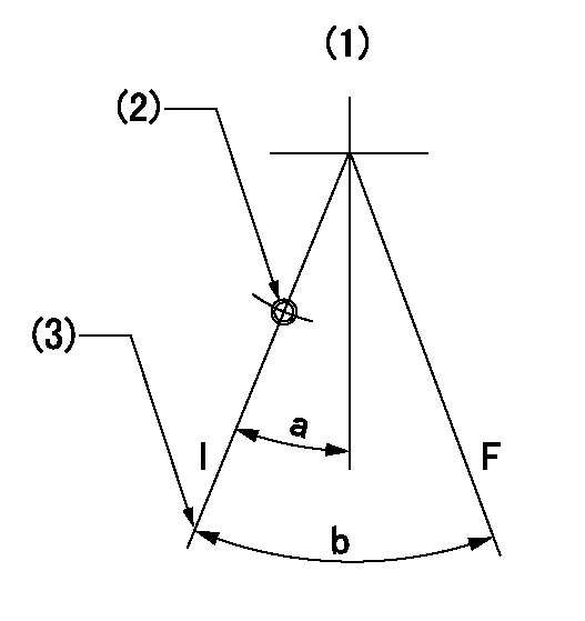
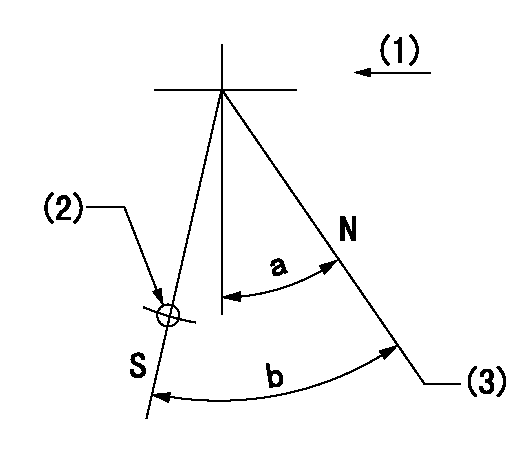
F:Full load
I:Idle
(1)Base lever only
(2)At threaded hole above R = aa
(3)Stopper bolt setting
----------
aa=31mm
----------
a=15deg+-5deg b=24.5deg+-3deg
----------
aa=31mm
----------
a=15deg+-5deg b=24.5deg+-3deg
Stop lever angle
N:Pump normal
S:Stop the pump.
(1)Drive side
(2)Use the hole at R = aa
(3)Rack position = bb (set the stopper bolt at point D).
----------
aa=50mm bb=12.3+0.2mm
----------
a=30deg+-5deg b=32deg+-5deg
----------
aa=50mm bb=12.3+0.2mm
----------
a=30deg+-5deg b=32deg+-5deg
Timing setting

(1)Pump vertical direction
(2)Coupling's key groove position at No 1 cylinder's beginning of injection
(3)-
(4)-
----------
----------
a=(20deg)
----------
----------
a=(20deg)
Information:
BRAKESAVER CONTROL VALVE IN FLOW CONTROL POSITION
1. Passage to oil filter. 2. Oil cooler. 3. Air line. 4. Oil inlet passage. 5. Valve spool. 6. Control valve body. 7. Differential pressure valve. 8. Poppet valve. 9. BrakeSaver. 10. BrakeSaver inlet pressure. 11. BrakeSaver outlet pressure.BrakeSaver Operator Controls
Two types of controls are available for the BrakeSaver: a manual control and an automatic control. Supply air goes into the circuit through pressure reducing valve (17). The pressure reducing valve keeps a maximum pressure in the control circuit of 40 psi (280 kPa).This pressure air is available at manual control lever (2) in the operator's compartment and at the solenoid valve (8). When ignition switch (5) is turned ON, the electrical circuit to manual-automatic switch (3) has current available. [Switch (3) is shown in the MANUAL position.] In the MANUAL position, switch (3) opens the circuit. The automatic section of switch (3) is in the OFF position and the BrakeSaver can only be operated manually. Maximum supply air pressure from the air compressor (not shown) is 125 psi (860 kPa).
BRAKESAVER CONTROL CIRCUIT SCHEMATIC
1. Pressure reducing valve. 2. Manual control lever. 3. Manual-automatic selector switch. 4. Control valve. 5. Ignition switch. 6. Double check valve. 7. Accelerator switch. 8. Solenoid valve. 9. Clutch switch.Manual Control
When the BrakeSaver manual-automatic selector switch (3) is in the MANUAL position, the BrakeSaver can only be turned on by the operator by moving manual control lever (2). With control lever (2) in the BrakeSaver ON position, air goes through manual control lever (2) and double check valve (6) to control valve (4). A valve spool moves and the BrakeSaver gets oil. It holds this oil until manual control lever (2) is moved to the BrakeSaver OFF position. Air can go from control valve (4) to the atmosphere through manual control lever (2).The farther control lever (2) is moved toward the ON position, the higher the pressure of the air sent to the control valve. An increase in air pressure in the control valve causes an increase in the oil pressure in the BrakeSaver. An increase in the oil pressure in the BrakeSaver causes an increase in the braking force in the BrakeSaver. The operator can give modulation to the braking force in the BrakeSaver through the movement of control lever (2).An air pressure gauge gives the operator a relative indication of the air pressure being sent to the control valve. Through the use of the indication on the air pressure gauge in relation to engine rpm, the operator can get approximately the same braking effect from the BrakeSaver time after time. This lets the operator more easily control the desired wheel speed of the vehicle.An oil temperature gauge gives the operator an indication of the ability of the engine cooling system to control the heat in the BrakeSaver during its operation. If the gauge reads too HOT, move control lever (2) to the OFF position and use the service brakes to control the wheel speed of the
Have questions with 106671-0596?
Group cross 106671-0596 ZEXEL
Nissan-Diesel
106671-0596
9 400 613 475
1671396774
INJECTION-PUMP ASSEMBLY
PE6T
PE6T