Information injection-pump assembly
BOSCH
9 400 612 425
9400612425
ZEXEL
106671-0595
1066710595
Rating:
Service parts 106671-0595 INJECTION-PUMP ASSEMBLY:
1.
_
7.
COUPLING PLATE
8.
_
9.
_
11.
Nozzle and Holder
16600-96520
12.
Open Pre:MPa(Kqf/cm2)
22.6{230}

15.
NOZZLE SET
Include in #1:
106671-0595
as INJECTION-PUMP ASSEMBLY
Cross reference number
BOSCH
9 400 612 425
9400612425
ZEXEL
106671-0595
1066710595
Zexel num
Bosch num
Firm num
Name
Calibration Data:
Adjustment conditions
Test oil
1404 Test oil ISO4113 or {SAEJ967d}
1404 Test oil ISO4113 or {SAEJ967d}
Test oil temperature
degC
40
40
45
Nozzle and nozzle holder
105780-8140
Bosch type code
EF8511/9A
Nozzle
105780-0000
Bosch type code
DN12SD12T
Nozzle holder
105780-2080
Bosch type code
EF8511/9
Opening pressure
MPa
17.2
Opening pressure
kgf/cm2
175
Injection pipe
Outer diameter - inner diameter - length (mm) mm 8-3-600
Outer diameter - inner diameter - length (mm) mm 8-3-600
Overflow valve
132424-0620
Overflow valve opening pressure
kPa
157
123
191
Overflow valve opening pressure
kgf/cm2
1.6
1.25
1.95
Tester oil delivery pressure
kPa
157
157
157
Tester oil delivery pressure
kgf/cm2
1.6
1.6
1.6
Direction of rotation (viewed from drive side)
Right R
Right R
Injection timing adjustment
Direction of rotation (viewed from drive side)
Right R
Right R
Injection order
1-4-2-6-
3-5
Pre-stroke
mm
3.65
3.6
3.7
Beginning of injection position
Drive side NO.1
Drive side NO.1
Difference between angles 1
Cal 1-4 deg. 60 59.5 60.5
Cal 1-4 deg. 60 59.5 60.5
Difference between angles 2
Cyl.1-2 deg. 120 119.5 120.5
Cyl.1-2 deg. 120 119.5 120.5
Difference between angles 3
Cal 1-6 deg. 180 179.5 180.5
Cal 1-6 deg. 180 179.5 180.5
Difference between angles 4
Cal 1-3 deg. 240 239.5 240.5
Cal 1-3 deg. 240 239.5 240.5
Difference between angles 5
Cal 1-5 deg. 300 299.5 300.5
Cal 1-5 deg. 300 299.5 300.5
Injection quantity adjustment
Adjusting point
A
Rack position
11.6
Pump speed
r/min
600
600
600
Average injection quantity
mm3/st.
154.8
152.8
156.8
Max. variation between cylinders
%
0
-4
4
Basic
*
Fixing the lever
*
Boost pressure
kPa
29.3
29.3
Boost pressure
mmHg
220
220
Injection quantity adjustment_02
Adjusting point
C
Rack position
10.4
Pump speed
r/min
300
300
300
Average injection quantity
mm3/st.
117.4
115.4
119.4
Fixing the lever
*
Boost pressure
kPa
0
0
0
Boost pressure
mmHg
0
0
0
Injection quantity adjustment_03
Adjusting point
E
Rack position
8.1+-0.5
Pump speed
r/min
250
250
250
Average injection quantity
mm3/st.
15
14
16
Max. variation between cylinders
%
0
-10
10
Fixing the rack
*
Boost pressure
kPa
0
0
0
Boost pressure
mmHg
0
0
0
Boost compensator adjustment
Pump speed
r/min
300
300
300
Rack position
10.4
Boost pressure
kPa
4
2.7
5.3
Boost pressure
mmHg
30
20
40
Boost compensator adjustment_02
Pump speed
r/min
300
300
300
Rack position
12.3+0.2
Boost pressure
kPa
16
16
16
Boost pressure
mmHg
120
120
120
Timer adjustment
Pump speed
r/min
1200--
Advance angle
deg.
0
0
0
Remarks
Start
Start
Timer adjustment_02
Pump speed
r/min
1150
Advance angle
deg.
0.5
Timer adjustment_03
Pump speed
r/min
-
Advance angle
deg.
2
2
2
Remarks
Measure the actual speed, stop
Measure the actual speed, stop
Test data Ex:
Governor adjustment
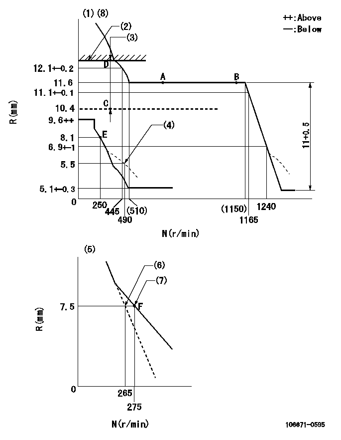
N:Pump speed
R:Rack position (mm)
(1)Tolerance for racks not indicated: +-0.05mm.
(2)Rack limit using the stop lever: R1
(3)Boost compensator stroke: BCL
(4)Damper spring setting
(5)Variable speed specification: idling adjustment
(6)Main spring setting
(7)Set idle sub-spring
(8)Perform governor adjustment at an ambient temperature of at least 15 deg C (boost compensator start spring is shape memory alloy).
----------
R1=12.3+0.2mm BCL=2+-0.1mm
----------
----------
R1=12.3+0.2mm BCL=2+-0.1mm
----------
Speed control lever angle
F:Full speed
I:Idle
(1)Stopper bolt setting
(2)Stopper bolt setting
(3)Set the pump speed at aa
----------
aa=275r/min
----------
a=23deg+-5deg b=17deg+-5deg
----------
aa=275r/min
----------
a=23deg+-5deg b=17deg+-5deg
0000000901
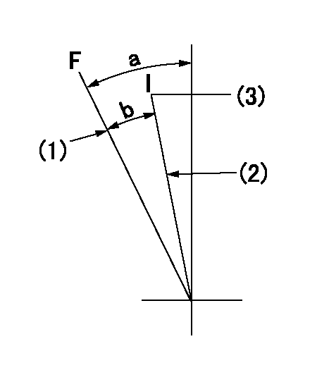
F:Full load
I:Idle
(1)At center of threaded hole above R = aa
(2)Stopper bolt setting
----------
aa=17mm
----------
a=15deg+-5deg b=24.5deg+-3deg
----------
aa=17mm
----------
a=15deg+-5deg b=24.5deg+-3deg
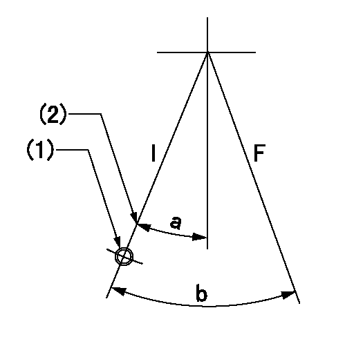
Stop lever angle
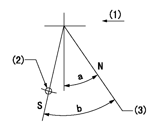
N:Pump normal
S:Stop the pump.
(1)Drive side
(2)Use the hole at R = aa
(3)Rack position bb
----------
aa=50mm bb=12.3+0.2mm
----------
a=30deg+-5deg b=32deg+-5deg
----------
aa=50mm bb=12.3+0.2mm
----------
a=30deg+-5deg b=32deg+-5deg
Timing setting

(1)Pump vertical direction
(2)Coupling's key groove position at No 1 cylinder's beginning of injection
(3)-
(4)-
----------
----------
a=(25deg)
----------
----------
a=(25deg)
Information:
Use 5P3519 Piston Ring Groove Gauge to check top and intermediate ring grooves with straight sides. For instructions on the use of the gauge, see the GUIDELINE FOR REUSABLE PARTS; PISTONS AND CYLINDER LINERS, Form No. SEBF8001.1P435 Piston Assembly
Maximum permissible clearance between ring and groove (all rings) ... .014 in.(0.36 mm)(1) Clearance between top ring and groove ... .0057 to .0071 in.(0.145 to 0.180 mm)(2) Clearance between center ring and groove ... .0030 to .0048 in.(0.076 to 0.122 mm)(3) Clearance between oil ring and groove ... .0015 to .0030 in.(0.038 to 0.076 mm)(4) Bore in piston for pin ... 2.0005 .0002 in.(50.813 0.005 mm) Clearance between pin and bore in piston (new) ... .0003 to .0010 in.(0.008 to 0.025 mm)Maximum permissible clearance between piston pin and bore in piston (worn) ... .002 in.(0.05 mm)Clearance between ends of piston ring, installed in cylinder liner with bore size of ... 5.400 to 5.402 in.(137.16 to 137.21 mm)*(5) Top ring ... .019 to .029 in.(0.48 to 0.74 mm)(6) Center ring ... .019 to .029 in.(0.48 to 0.74 mm)(7) Oil ring ... .015 to .025 in.(0.38 to 0.64 mm) ... .003 in.(0.08 mm)*Increase in clearance between ends of piston rings for each .001 in. (0.03 mm) increase in size of bore of the cylinder liner 9S2266 Piston Assembly
Maximum permissible clearance between ring and groove (all rings) ... .006 in.(0.15 mm)(1) Clearance between top ring and groove ... .0055 to .0073 in.(0.140 to 0.185 mm)(2) Clearance between center ring and groove ... .0030 to .0048 in.(0.076 to 0.122 mm)(3) Clearance between oil ring and groove ... .0015 to .0030 in.(0.038 to 0.076 mm)(4) Bore in piston for pin ... 2.0005 .0002 in.(50.813 0.005 mm) Clearance between pin and bore in piston ... .0003 to .0010 in.(0.008 to 0.025 mm)Maximum permissible clearance between piston pin and bore in piston ... .002 in.(0.05 mm)Clearance between ends of piston ring, installed in cylinder liner with bore size of ... 5.400 to 5.402 in.(137.16 to 173.21 mm)*(5) Top ring ... .021 to .027 in.(0.53 to 0.69 mm)(6) Center ring ... .019 to .029 in.(0.48 to 0.74 mm)(7) Oil ring ... .015 to .025 in.(0.38 to 0.64 mm) ... .003 in.(0.08 mm)*Increase in clearance between ends of piston rings for each .001 in. (0.03 mm) increase in size of bore of the cylinder liner 9L6054 And 9N2875 Piston Assemblies
Make reference to GUIDELINE FOR REUSABLE PARTS; PISTONS AND CYLINDER LINERS, Form No. SEBF8001. (4) Bore in piston for pin ... 2.0005 .0002 in.(50.81 0.005 mm) Clearance between pin and bore in piston ... .0007 .0004 in.(0.018 0.010 mm)Maximum permissible clearance (worn) ... .002 in.(0.05 mm)Pin diameter ... 1.9998 .0002 in.(50.795 0.005 mm) When installed in the engine, the "V" mark on top of the piston must be in alignment with the "V"