Information injection-pump assembly
ZEXEL
106671-0380
1066710380

Rating:
Cross reference number
ZEXEL
106671-0380
1066710380
Zexel num
Bosch num
Firm num
Name
106671-0380
INJECTION-PUMP ASSEMBLY
Calibration Data:
Adjustment conditions
Test oil
1404 Test oil ISO4113 or {SAEJ967d}
1404 Test oil ISO4113 or {SAEJ967d}
Test oil temperature
degC
40
40
45
Nozzle and nozzle holder
105780-8140
Bosch type code
EF8511/9A
Nozzle
105780-0000
Bosch type code
DN12SD12T
Nozzle holder
105780-2080
Bosch type code
EF8511/9
Opening pressure
MPa
17.2
Opening pressure
kgf/cm2
175
Injection pipe
Outer diameter - inner diameter - length (mm) mm 8-3-600
Outer diameter - inner diameter - length (mm) mm 8-3-600
Overflow valve opening pressure
kPa
157
123
191
Overflow valve opening pressure
kgf/cm2
1.6
1.25
1.95
Tester oil delivery pressure
kPa
157
157
157
Tester oil delivery pressure
kgf/cm2
1.6
1.6
1.6
Direction of rotation (viewed from drive side)
Right R
Right R
Injection timing adjustment
Direction of rotation (viewed from drive side)
Right R
Right R
Injection order
1-4-2-6-
3-5
Pre-stroke
mm
3.65
3.6
3.7
Beginning of injection position
Drive side NO.1
Drive side NO.1
Difference between angles 1
Cal 1-4 deg. 60 59.5 60.5
Cal 1-4 deg. 60 59.5 60.5
Difference between angles 2
Cyl.1-2 deg. 120 119.5 120.5
Cyl.1-2 deg. 120 119.5 120.5
Difference between angles 3
Cal 1-6 deg. 180 179.5 180.5
Cal 1-6 deg. 180 179.5 180.5
Difference between angles 4
Cal 1-3 deg. 240 239.5 240.5
Cal 1-3 deg. 240 239.5 240.5
Difference between angles 5
Cal 1-5 deg. 300 299.5 300.5
Cal 1-5 deg. 300 299.5 300.5
Injection quantity adjustment
Adjusting point
A
Rack position
R2(11.7)
Pump speed
r/min
1000
1000
1000
Average injection quantity
mm3/st.
158.6
154.6
162.6
Max. variation between cylinders
%
0
-5
5
Fixing the lever
*
Boost pressure
kPa
33.3
33.3
Boost pressure
mmHg
250
250
Injection quantity adjustment_02
Adjusting point
B
Rack position
12.1
Pump speed
r/min
600
600
600
Average injection quantity
mm3/st.
170.1
168.1
172.1
Max. variation between cylinders
%
0
-4
4
Basic
*
Fixing the lever
*
Boost pressure
kPa
33.3
33.3
Boost pressure
mmHg
250
250
Injection quantity adjustment_03
Adjusting point
C
Rack position
7.4+-0.5
Pump speed
r/min
225
225
225
Average injection quantity
mm3/st.
10.1
9.1
11.1
Max. variation between cylinders
%
0
-10
10
Fixing the rack
*
Boost pressure
kPa
0
0
0
Boost pressure
mmHg
0
0
0
Injection quantity adjustment_04
Adjusting point
D
Rack position
R1(10.9)
Pump speed
r/min
300
300
300
Average injection quantity
mm3/st.
126.5
124.5
128.5
Fixing the lever
*
Boost pressure
kPa
0
0
0
Boost pressure
mmHg
0
0
0
Injection quantity adjustment_05
Adjusting point
E
Rack position
12.5
Pump speed
r/min
300
300
300
Average injection quantity
mm3/st.
176.1
166.1
186.1
Fixing the lever
*
Rack limit
*
Boost compensator adjustment
Pump speed
r/min
300
300
300
Rack position
R1(10.9)
Boost pressure
kPa
4
Boost pressure
mmHg
30
Boost compensator adjustment_02
Pump speed
r/min
300
300
300
Rack position
12.5
Boost pressure
kPa
20
20
20
Boost pressure
mmHg
150
150
150
Timer adjustment
Pump speed
r/min
200+100
Advance angle
deg.
1.6
1.1
2.1
Remarks
Start
Start
Timer adjustment_02
Pump speed
r/min
500-150
Advance angle
deg.
0
0
0
Timer adjustment_03
Pump speed
r/min
820
Advance angle
deg.
0.5
Timer adjustment_04
Pump speed
r/min
1100
Advance angle
deg.
2
1.5
2.5
Remarks
Finish
Finish
Test data Ex:
Governor adjustment
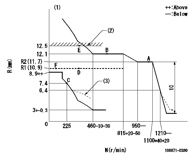
N:Pump speed
R:Rack position (mm)
(1)Perform governor adjustment at an ambient temperature of at least 15 deg C (boost compensator start spring is shape memory alloy).
(2)Rack limit using stop lever
(3)Damper spring setting: DL
----------
DL=6.4-0.2mm
----------
----------
DL=6.4-0.2mm
----------
Speed control lever angle

F:Full speed
----------
----------
a=30deg+-5deg
----------
----------
a=30deg+-5deg
0000000901
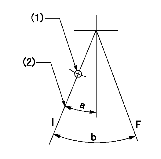
F:Full load
I:Idle
(1)At threaded hole above R = aa
(2)Stopper bolt setting
----------
aa=17mm
----------
a=22deg+-5deg b=33deg+-3deg
----------
aa=17mm
----------
a=22deg+-5deg b=33deg+-3deg
Stop lever angle
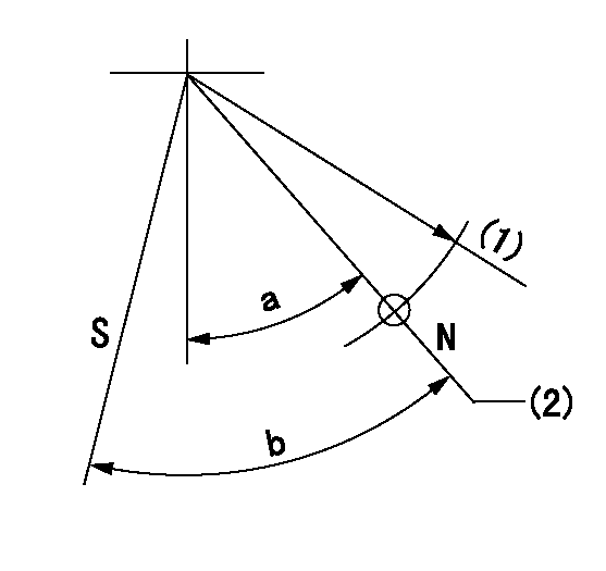
N:Pump normal
S:Stop the pump.
(1)R = aa
(2)Rack position bb
----------
aa=50mm bb=12.5mm
----------
a=30deg+-5deg b=32deg+-5deg
----------
aa=50mm bb=12.5mm
----------
a=30deg+-5deg b=32deg+-5deg
Timing setting

(1)Pump vertical direction
(2)Coupling's key groove position at No 1 cylinder's beginning of injection
(3)-
(4)-
----------
----------
a=(30deg)
----------
----------
a=(30deg)
Information:
start by:a) remove oil pump1. Remove bolt and washer that hold gear on the shaft. 2. Use tooling (A) to remove drive gear (1) from shaft. Remove the key from shaft. 3. Remove retainer (3) for bypass valve.4. Remove spring and bypass valve.5. Remove the cover (2) from pump body. 6. Use tooling (B) to remove bearings from the cover. 7. Remove gears (5) from pump body (4).8. Use tooling (B) to remove bearings from pump body.Assemble Oil Pump
1. Use tooling (A) to install the bearings in the main pump body until they are even with the outside surface of the pump body. Install the bearings so the junctions in the bearings are 30° 15° from the center of the bearing bores and toward the oil pump outlet passage (2) as shown. 2. Install idler gear (1) and drive gear (3) in the oil pump body. Put clean oil on the bearings and gears. 3. Use tooling (A) to install the bearings in cover (4) until they are even with the outside surface of the cover. Install the bearings so the junctions in the bearings are 30° 15° from the center of the bearing bores and toward the oil pump outlet passage as shown. 4. Install bypass valve (5), spring (6), spacer and the retainer in the pump body.5. Install the key on the shaft. 6. Install gear (7) on the shaft. Install the washer and bolt that holds the gear on the shaft.7. Make sure the pump turns freely by hand after it is assembled.end by:a) install oil pump
1. Use tooling (A) to install the bearings in the main pump body until they are even with the outside surface of the pump body. Install the bearings so the junctions in the bearings are 30° 15° from the center of the bearing bores and toward the oil pump outlet passage (2) as shown. 2. Install idler gear (1) and drive gear (3) in the oil pump body. Put clean oil on the bearings and gears. 3. Use tooling (A) to install the bearings in cover (4) until they are even with the outside surface of the cover. Install the bearings so the junctions in the bearings are 30° 15° from the center of the bearing bores and toward the oil pump outlet passage as shown. 4. Install bypass valve (5), spring (6), spacer and the retainer in the pump body.5. Install the key on the shaft. 6. Install gear (7) on the shaft. Install the washer and bolt that holds the gear on the shaft.7. Make sure the pump turns freely by hand after it is assembled.end by:a) install oil pump
Have questions with 106671-0380?
Group cross 106671-0380 ZEXEL
Nissan-Diesel
Nissan-Diesel
Nissan-Diesel
Nissan-Diesel
Nissan-Diesel
Nissan-Diesel
Nissan-Diesel
Nissan-Diesel
Nissan-Diesel
106671-0380
INJECTION-PUMP ASSEMBLY