Information injection-pump assembly
ZEXEL
106671-0370
1066710370

Rating:
Cross reference number
ZEXEL
106671-0370
1066710370
Zexel num
Bosch num
Firm num
Name
106671-0370
INJECTION-PUMP ASSEMBLY
Calibration Data:
Adjustment conditions
Test oil
1404 Test oil ISO4113 or {SAEJ967d}
1404 Test oil ISO4113 or {SAEJ967d}
Test oil temperature
degC
40
40
45
Nozzle and nozzle holder
105780-8140
Bosch type code
EF8511/9A
Nozzle
105780-0000
Bosch type code
DN12SD12T
Nozzle holder
105780-2080
Bosch type code
EF8511/9
Opening pressure
MPa
17.2
Opening pressure
kgf/cm2
175
Injection pipe
Outer diameter - inner diameter - length (mm) mm 8-3-600
Outer diameter - inner diameter - length (mm) mm 8-3-600
Overflow valve
132424-0620
Overflow valve opening pressure
kPa
157
123
191
Overflow valve opening pressure
kgf/cm2
1.6
1.25
1.95
Tester oil delivery pressure
kPa
157
157
157
Tester oil delivery pressure
kgf/cm2
1.6
1.6
1.6
Direction of rotation (viewed from drive side)
Right R
Right R
Injection timing adjustment
Direction of rotation (viewed from drive side)
Right R
Right R
Injection order
1-4-2-6-
3-5
Pre-stroke
mm
3.65
3.6
3.7
Beginning of injection position
Drive side NO.1
Drive side NO.1
Difference between angles 1
Cal 1-4 deg. 60 59.5 60.5
Cal 1-4 deg. 60 59.5 60.5
Difference between angles 2
Cyl.1-2 deg. 120 119.5 120.5
Cyl.1-2 deg. 120 119.5 120.5
Difference between angles 3
Cal 1-6 deg. 180 179.5 180.5
Cal 1-6 deg. 180 179.5 180.5
Difference between angles 4
Cal 1-3 deg. 240 239.5 240.5
Cal 1-3 deg. 240 239.5 240.5
Difference between angles 5
Cal 1-5 deg. 300 299.5 300.5
Cal 1-5 deg. 300 299.5 300.5
Injection quantity adjustment
Adjusting point
A
Rack position
R2(11.5)
Pump speed
r/min
1100
1100
1100
Average injection quantity
mm3/st.
154.3
150.3
158.3
Max. variation between cylinders
%
0
-5
5
Fixing the lever
*
Boost pressure
kPa
30.7
30.7
Boost pressure
mmHg
230
230
Injection quantity adjustment_02
Adjusting point
B
Rack position
12.3
Pump speed
r/min
600
600
600
Average injection quantity
mm3/st.
174.4
172.4
176.4
Max. variation between cylinders
%
0
-4
4
Basic
*
Fixing the lever
*
Boost pressure
kPa
30.7
30.7
Boost pressure
mmHg
230
230
Injection quantity adjustment_03
Adjusting point
C
Rack position
7.4+-0.5
Pump speed
r/min
225
225
225
Average injection quantity
mm3/st.
10.1
9.1
11.1
Max. variation between cylinders
%
0
-10
10
Fixing the rack
*
Boost pressure
kPa
0
0
0
Boost pressure
mmHg
0
0
0
Injection quantity adjustment_04
Adjusting point
D
Rack position
R1(10.7)
Pump speed
r/min
300
300
300
Average injection quantity
mm3/st.
120.6
118.6
122.6
Fixing the lever
*
Boost pressure
kPa
0
0
0
Boost pressure
mmHg
0
0
0
Injection quantity adjustment_05
Adjusting point
E
Rack position
12.3+0.2
Pump speed
r/min
300
300
300
Average injection quantity
mm3/st.
173.8
163.8
183.8
Fixing the lever
*
Rack limit
*
Boost compensator adjustment
Pump speed
r/min
300
300
300
Rack position
R1(10.7)
Boost pressure
kPa
4
Boost pressure
mmHg
30
Boost compensator adjustment_02
Pump speed
r/min
300
300
300
Rack position
12.3+0.2
Boost pressure
kPa
17.3
17.3
17.3
Boost pressure
mmHg
130
130
130
Timer adjustment
Pump speed
r/min
200+100
Advance angle
deg.
1.6
1.1
2.1
Remarks
Start
Start
Timer adjustment_02
Pump speed
r/min
500-150
Advance angle
deg.
0
0
0
Timer adjustment_03
Pump speed
r/min
(900)
Advance angle
deg.
0
0
0
Timer adjustment_04
Pump speed
r/min
1100
Advance angle
deg.
3
2.5
3.5
Remarks
Finish
Finish
Test data Ex:
Governor adjustment
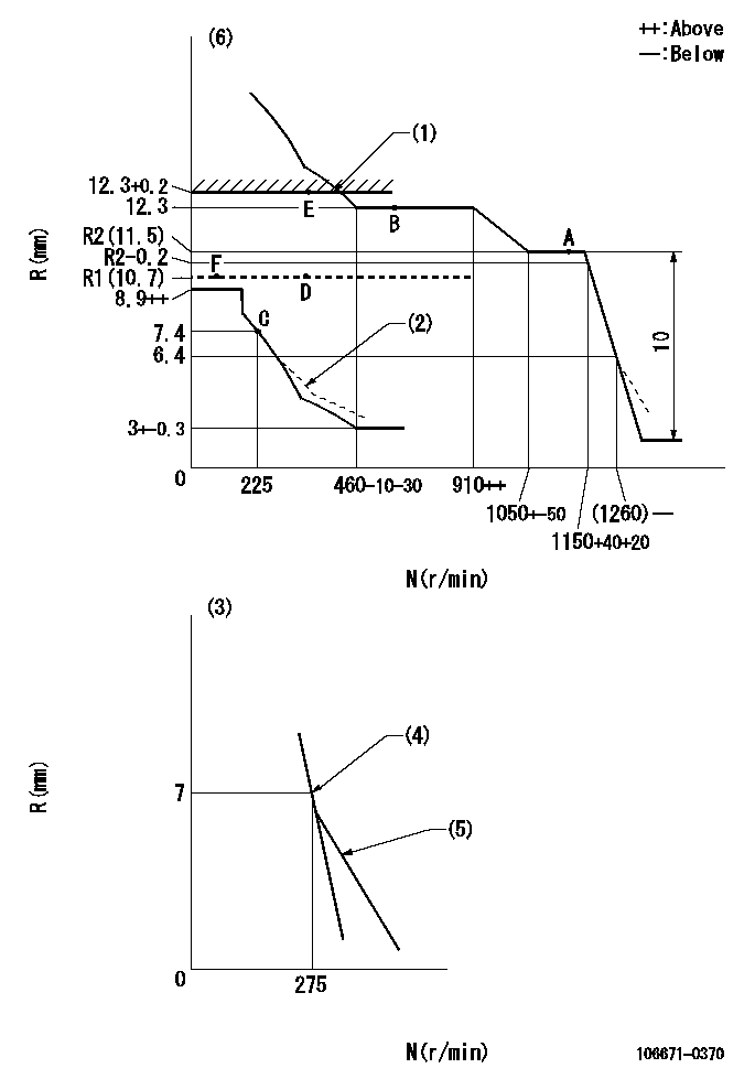
N:Pump speed
R:Rack position (mm)
(1)Rack limit using stop lever
(2)Damper spring setting: DL
(3)Variable speed specification: idling adjustment
(4)Main spring setting
(5)Idle sub spring setting: L1.
(6)Perform governor adjustment at an ambient temperature of at least 15 deg C (boost compensator start spring is shape memory alloy).
----------
DL=6.4-0.2mm L1=7-0.2mm
----------
----------
DL=6.4-0.2mm L1=7-0.2mm
----------
Speed control lever angle
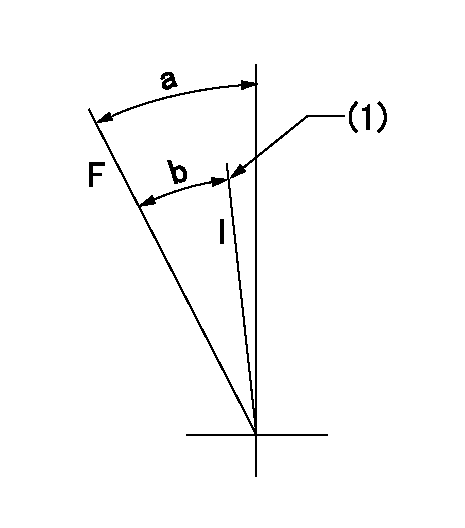
F:Full speed
I:Idle
(1)Stopper bolt setting
----------
----------
a=31deg+-5deg b=(24deg)+-5deg
----------
----------
a=31deg+-5deg b=(24deg)+-5deg
0000000901

F:Full load
I:Idle
(1)Stopper bolt setting
(2)At threaded hole above R = aa
----------
aa=17mm
----------
a=22deg+-5deg b=34.5deg+-3deg
----------
aa=17mm
----------
a=22deg+-5deg b=34.5deg+-3deg
Stop lever angle
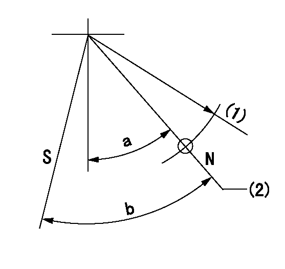
N:Pump normal
S:Stop the pump.
(1)R = aa
(2)Rack position bb
----------
aa=50mm bb=12.3+0.2mm
----------
a=30deg+-5deg b=32deg+-5deg
----------
aa=50mm bb=12.3+0.2mm
----------
a=30deg+-5deg b=32deg+-5deg
Timing setting

(1)Pump vertical direction
(2)Coupling's key groove position at No 1 cylinder's beginning of injection
(3)-
(4)-
----------
----------
a=(30deg)
----------
----------
a=(30deg)
Information:
2. Remove two short bolts (1) and two longer bolts (2) from manifold (3) and BrakeSaver housing.3. Remove the manifold from the control valve. 4. Remove the three bolts from elbows (5) and the control valve.5. Remove four bolts (4) that hold the control valve to the oil pan.6. Remove the control valve from under the oil pan.7. Make an inspection of the O-ring seals on the manifold and on the control valve. If there is wear or damage make a replacement of the O-ring seals.Install Brakesaver Control Valve
1. Put clean SAE 30 engine oil on O-ring seals (1).2. Put the control valve in position under the oil pan. Install the four bolts that hold the control valve to the oil pan.3. Install the elbow and the bolts that hold it to the side of the control valve. 4. Put SAE 30 engine oil on the O-ring seals of the manifold. Install manifold (2) in the control valve. Install the four bolts that hold the manifold to the BrakeSaver housing.5. Fill the engine with oil. See 3408 TRUCK ENGINE LUBRICATION AND MAINTENANCE GUIDE.Disassemble Brakesaver Control Valve
start by:a) remove BrakeSaver control valve 1. Remove O-ring seals (1) from the valve body.2. Remove four bolts (2) slowly and evenly from cover (4). Remove the cover.
Spring force is behind the cover at removal.
3. Remove cover (3) and the seal from the opposite end of the valve body. 4. Remove spool (8) as an assembly.5. Remove spring (7), stop (10), spring (6) and slug (9).6. Remove the seals and sleeve (5). 7. Remove bolt (11), plate (13) and diaphragm (12) from the spool. Make an inspection of the pin on the spool, and make a replacement of the pin if there is damage or wear.Assemble Brakesaver Control Valve
1. Install diaphragm (4) and plate (8) on valve spool (3). Make alignment of the hole in the plate valve with the pin on the spool. Install the bolt that holds the plate and the diaphragm in position.
When diaphragm (4) is installed on valve spool (3), make sure the fabric side is pulled down over the valve spool to make contact with it and the smooth (rubber coated) side is next to valve body.
2. Install sleeves (1) and the seals in the valve body. 3. Install the valve spool as an assembly into the valve body. As the valve spool is installed, make sure the edge of the diaphragm makes contact all the way around with the groove in the valve body. At this time the valve spool end must extend about 1.50 in. (38.1 mm) from the valve body. Push the valve spool about .25 in. (6.4 mm) - .50 in. (12.7 mm) farther into the valve body until a curved depression is caused between the valve spool and valve body. Make sure there are no wrinkles in the diaphragm. 4. Put cover (9) in position. Install the four bolts that hold the cover on the valve body. Move the valve spool in the
Have questions with 106671-0370?
Group cross 106671-0370 ZEXEL
Nissan-Diesel
Nissan-Diesel
Nissan-Diesel
Nissan-Diesel
Nissan-Diesel
Nissan-Diesel
Nissan-Diesel
Nissan-Diesel
106671-0370
INJECTION-PUMP ASSEMBLY