Information injection-pump assembly
BOSCH
9 400 616 656
9400616656
ZEXEL
106671-0263
1066710263
NISSAN-DIESEL
1680196561
1680196561

Rating:
Service parts 106671-0263 INJECTION-PUMP ASSEMBLY:
1.
_
7.
COUPLING PLATE
8.
_
9.
_
10.
NOZZLE AND HOLDER ASSY
11.
Nozzle and Holder
12.
Open Pre:MPa(Kqf/cm2)
13.
NOZZLE-HOLDER
14.
NOZZLE
15.
NOZZLE SET
Include in #1:
106671-0263
as INJECTION-PUMP ASSEMBLY
Cross reference number
BOSCH
9 400 616 656
9400616656
ZEXEL
106671-0263
1066710263
NISSAN-DIESEL
1680196561
1680196561
Zexel num
Bosch num
Firm num
Name
106671-0263
9 400 616 656
1680196561 NISSAN-DIESEL
INJECTION-PUMP ASSEMBLY
PE6T * K
PE6T * K
Calibration Data:
Adjustment conditions
Test oil
1404 Test oil ISO4113 or {SAEJ967d}
1404 Test oil ISO4113 or {SAEJ967d}
Test oil temperature
degC
40
40
45
Nozzle and nozzle holder
105780-8140
Bosch type code
EF8511/9A
Nozzle
105780-0000
Bosch type code
DN12SD12T
Nozzle holder
105780-2080
Bosch type code
EF8511/9
Opening pressure
MPa
17.2
Opening pressure
kgf/cm2
175
Injection pipe
Outer diameter - inner diameter - length (mm) mm 8-3-600
Outer diameter - inner diameter - length (mm) mm 8-3-600
Overflow valve
132424-0620
Overflow valve opening pressure
kPa
157
123
191
Overflow valve opening pressure
kgf/cm2
1.6
1.25
1.95
Tester oil delivery pressure
kPa
157
157
157
Tester oil delivery pressure
kgf/cm2
1.6
1.6
1.6
RED3 control unit part number
407910-2
470
RED3 rack sensor specifications
mm
15
Direction of rotation (viewed from drive side)
Right R
Right R
Injection timing adjustment
Direction of rotation (viewed from drive side)
Right R
Right R
Injection order
1-4-2-6-
3-5
Pre-stroke
mm
3.65
3.6
3.7
Beginning of injection position
Drive side NO.1
Drive side NO.1
Difference between angles 1
Cal 1-4 deg. 60 59.5 60.5
Cal 1-4 deg. 60 59.5 60.5
Difference between angles 2
Cyl.1-2 deg. 120 119.5 120.5
Cyl.1-2 deg. 120 119.5 120.5
Difference between angles 3
Cal 1-6 deg. 180 179.5 180.5
Cal 1-6 deg. 180 179.5 180.5
Difference between angles 4
Cal 1-3 deg. 240 239.5 240.5
Cal 1-3 deg. 240 239.5 240.5
Difference between angles 5
Cal 1-5 deg. 300 299.5 300.5
Cal 1-5 deg. 300 299.5 300.5
Injection quantity adjustment
Rack position
(11.8)
Vist
V
1.64
1.64
1.64
Pump speed
r/min
600
600
600
Average injection quantity
mm3/st.
174.4
172.4
176.4
Max. variation between cylinders
%
0
-4
4
Basic
*
Injection quantity adjustment_02
Rack position
(7.1)
Vist
V
2.58
2.48
2.68
Pump speed
r/min
225
225
225
Average injection quantity
mm3/st.
10.1
9.1
11.1
Max. variation between cylinders
%
0
-10
10
Governor adjustment
Pump speed
r/min
200+100
Advance angle
deg.
1.6
1.1
2.1
Remarks
Start
Start
Governor adjustment_02
Pump speed
r/min
500-150
Advance angle
deg.
0
0
0
Governor adjustment_03
Pump speed
r/min
(900)
Advance angle
deg.
0
0
0
Governor adjustment_04
Pump speed
r/min
1100
Advance angle
deg.
3
2.5
3.5
Remarks
Finish
Finish
Test data Ex:
Speed control lever angle
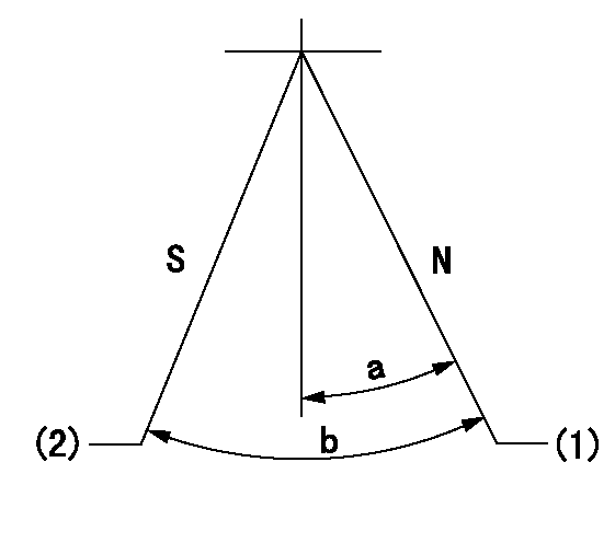
N:Pump normal
S:Stop the pump.
(1)Rack position = aa
(2)Rack position bb
----------
aa=16mm bb=1mm
----------
a=12deg+-5deg b=29deg+-5deg
----------
aa=16mm bb=1mm
----------
a=12deg+-5deg b=29deg+-5deg
0000000901

(1)Pump vertical direction
(2)Coupling's key groove position at No 1 cylinder's beginning of injection
(3)-
(4)-
----------
----------
a=(20deg)
----------
----------
a=(20deg)
Stop lever angle

(Rs) rack sensor specifications
(C/U) control unit part number
(V) Rack sensor output voltage
(R) Rack position (mm)
1. Confirming governor output characteristics (rack 15 mm, span 6 mm)
(1)When the output voltages of the rack sensor are V1 and V2, check that the rack positions R1 and R2 in the table above are satisfied.
----------
----------
----------
----------
Information:
start by:a) remove turbocharger1. Put identification marks on the two housings and the cartridge assembly for use at assembly. 2. Remove two clamps (3) and make a separation of compressor housing (1) and turbine housing (2) from the cartridge assembly.
When the nut is loosened, do not put a side force on the shaft.
3. Put cartridge assembly (4) in position on tooling (A). Remove the nut from the shaft. 4. Use a press to push the shaft assembly out of the cartridge assembly. Remove compressor wheel (5). 5. Remove seal ring (8) and shroud (7) from shaft assembly (6). 6. Remove snap ring (9) with tool (B). 7. Use two screwdrivers to remove insert (10) from the cartridge housing. 8. Remove O-ring seal (12) from the insert.9. Remove sleeve (11) from the insert. Remove the seal ring from the sleeve. 10. Remove deflector (13) from the housing. 11. Remove bearing (14) from the cartridge housing. 12. Remove sleeve (15) and bearing (16) from the cartridge housing. 13. Remove ring (17). 14. Use tool (C) to remove snap ring (19), bearing (18) and snap ring (20) from the cartridge housing. 15. Turn the cartridge housing over. Use tool (C) to remove snap ring (22), bearing (21) and snap ring (23) from the housing.Assemble Turbocharger (Schwitzer 4MF)
1. Make sure all oil passages are open and clean. Put clean engine oil on all parts before assembly. 2. Use tool (A) to install snap ring (2), bearing (3) and snap ring (1) in the housing. Install the snap rings with the round side toward the bearing. 3. Turn the housing over. Use tool (A) to install snap ring (5), bearing (6) and snap ring (4). Install the snap rings with the round side toward the bearing. 4. Put ring (7) in position in the housing. 5. Put bearing (8) in position. Make an alignment of the holes in the bearing with the dowels in the housing. Grooved side of the bearing must be up.6. Put sleeve (9) in position in the housing. 7. Put ring (10) in position on top of the bearing. 8. Install deflector (11) as shown. 9. Put seal ring (13) in position on sleeve (12). Install the sleeve in insert (15).10. Put O-ring seal (14) in position on the insert. 11. Put insert assembly (16) in position in the housing. 12. Use tool (B) to install snap ring (17) in the housing. 13. Put shaft assembly (18) in position on tooling (C).14. Put 6V2055 High Vacuum Grease in the seal ring groove on the shaft assembly.15. Install seal ring (19) on shaft assembly (18). 16. Put shroud (20) in position on the shaft assembly.17. Put cartridge housing (22) and compressor wheel (21) in position on the shaft assembly.
Do not put a side force on the shaft when the nut is tightened.
18. Put a small amount of oil on the face of the compressor wheel that will be under the nut. Install the nut and tighten it to a torque
Have questions with 106671-0263?
Group cross 106671-0263 ZEXEL
Nissan-Diesel
Nissan-Diesel
Nissan-Diesel
Nissan-Diesel
Nissan-Diesel
Nissan-Diesel
106671-0263
9 400 616 656
1680196561
INJECTION-PUMP ASSEMBLY
PE6T
PE6T