Information injection-pump assembly
ZEXEL
106671-0245
1066710245
Rating:
Service parts 106671-0245 INJECTION-PUMP ASSEMBLY:
1.
_
7.
COUPLING PLATE
8.
_
9.
_
11.
Nozzle and Holder
12.
Open Pre:MPa(Kqf/cm2)
17.7(180)/22.6(230)

15.
NOZZLE SET
Include in #1:
106671-0245
as INJECTION-PUMP ASSEMBLY
Cross reference number
ZEXEL
106671-0245
1066710245
Zexel num
Bosch num
Firm num
Name
106671-0245
INJECTION-PUMP ASSEMBLY
Calibration Data:
Adjustment conditions
Test oil
1404 Test oil ISO4113 or {SAEJ967d}
1404 Test oil ISO4113 or {SAEJ967d}
Test oil temperature
degC
40
40
45
Nozzle and nozzle holder
105780-8140
Bosch type code
EF8511/9A
Nozzle
105780-0000
Bosch type code
DN12SD12T
Nozzle holder
105780-2080
Bosch type code
EF8511/9
Opening pressure
MPa
17.2
Opening pressure
kgf/cm2
175
Injection pipe
Outer diameter - inner diameter - length (mm) mm 8-3-600
Outer diameter - inner diameter - length (mm) mm 8-3-600
Overflow valve opening pressure
kPa
157
123
191
Overflow valve opening pressure
kgf/cm2
1.6
1.25
1.95
Tester oil delivery pressure
kPa
157
157
157
Tester oil delivery pressure
kgf/cm2
1.6
1.6
1.6
Direction of rotation (viewed from drive side)
Right R
Right R
Injection timing adjustment
Direction of rotation (viewed from drive side)
Right R
Right R
Injection order
1-4-2-6-
3-5
Pre-stroke
mm
3.65
3.6
3.7
Beginning of injection position
Drive side NO.1
Drive side NO.1
Difference between angles 1
Cal 1-4 deg. 60 59.5 60.5
Cal 1-4 deg. 60 59.5 60.5
Difference between angles 2
Cyl.1-2 deg. 120 119.5 120.5
Cyl.1-2 deg. 120 119.5 120.5
Difference between angles 3
Cal 1-6 deg. 180 179.5 180.5
Cal 1-6 deg. 180 179.5 180.5
Difference between angles 4
Cal 1-3 deg. 240 239.5 240.5
Cal 1-3 deg. 240 239.5 240.5
Difference between angles 5
Cal 1-5 deg. 300 299.5 300.5
Cal 1-5 deg. 300 299.5 300.5
Injection quantity adjustment
Adjusting point
A
Rack position
R2(12.5)
Pump speed
r/min
1100
1100
1100
Average injection quantity
mm3/st.
185.6
181.6
189.6
Max. variation between cylinders
%
0
-5
5
Fixing the lever
*
Boost pressure
kPa
33.3
33.3
Boost pressure
mmHg
250
250
Injection quantity adjustment_02
Adjusting point
B
Rack position
12.1
Pump speed
r/min
600
600
600
Average injection quantity
mm3/st.
171
169
173
Max. variation between cylinders
%
0
-4
4
Basic
*
Fixing the lever
*
Boost pressure
kPa
33.3
33.3
Boost pressure
mmHg
250
250
Injection quantity adjustment_03
Adjusting point
C
Rack position
7.4+-0.5
Pump speed
r/min
225
225
225
Average injection quantity
mm3/st.
10.1
9.1
11.1
Max. variation between cylinders
%
0
-10
10
Fixing the rack
*
Boost pressure
kPa
0
0
0
Boost pressure
mmHg
0
0
0
Injection quantity adjustment_04
Adjusting point
E
Rack position
R2(12.5)
+0.2
Pump speed
r/min
300
300
300
Average injection quantity
mm3/st.
186.3
176.3
196.3
Fixing the lever
*
Rack limit
*
Boost compensator adjustment
Pump speed
r/min
300
300
300
Rack position
10.5
Boost pressure
kPa
4
2.7
4
Boost pressure
mmHg
30
20
30
Boost compensator adjustment_02
Pump speed
r/min
300
300
300
Rack position
12+-0.2
Boost pressure
kPa
14.7
14.7
14.7
Boost pressure
mmHg
110
110
110
Boost compensator adjustment_03
Pump speed
r/min
300
300
300
Rack position
R2(12.5)
+0.2
Boost pressure
kPa
20
20
20
Boost pressure
mmHg
150
150
150
Test data Ex:
Governor adjustment
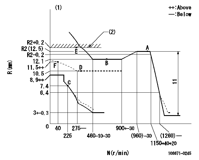
N:Pump speed
R:Rack position (mm)
(1)Damper spring setting: DL
(2)Rack limit using stop lever
----------
DL=6.4-0.2mm
----------
----------
DL=6.4-0.2mm
----------
Timer adjustment

(1)Adjusting range
(2)Step response time
(N): Speed of the pump
(L): Load
(theta) Advance angle
(Srd1) Step response time 1
(Srd2) Step response time 2
1. Adjusting conditions for the variable timer
(1)Adjust the clearance between the pickup and the protrusion to L.
----------
L=1-0.2mm N2=800r/min C2=(6.5)deg t1=2--sec. t2=2--sec.
----------
N1=1250++r/min P1=0kPa(0kgf/cm2) P2=392kPa(4kgf/cm2) C1=6.5+-0.3deg R01=0/4load R02=4/4load
----------
L=1-0.2mm N2=800r/min C2=(6.5)deg t1=2--sec. t2=2--sec.
----------
N1=1250++r/min P1=0kPa(0kgf/cm2) P2=392kPa(4kgf/cm2) C1=6.5+-0.3deg R01=0/4load R02=4/4load
Speed control lever angle

F:Full speed
----------
----------
a=(31deg)+-5deg
----------
----------
a=(31deg)+-5deg
0000000901
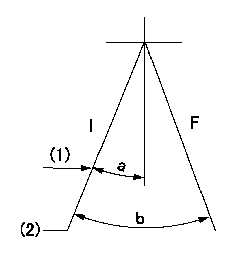
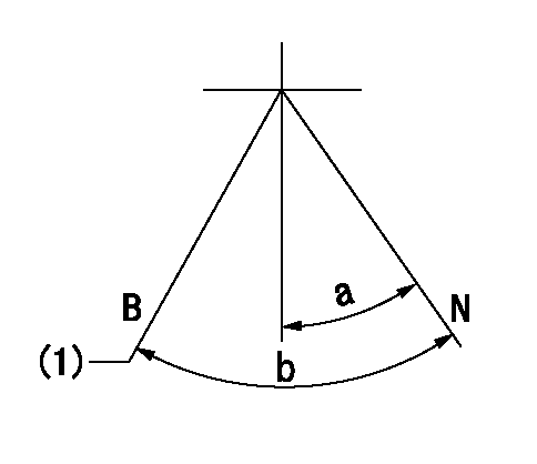
F:Full load
I:Idle
(1)Stopper bolt setting
(2)At center of threaded hole above R = aa
----------
aa=17mm
----------
a=22deg+-5deg b=33deg+-3deg
----------
aa=17mm
----------
a=22deg+-5deg b=33deg+-3deg
Stop lever angle
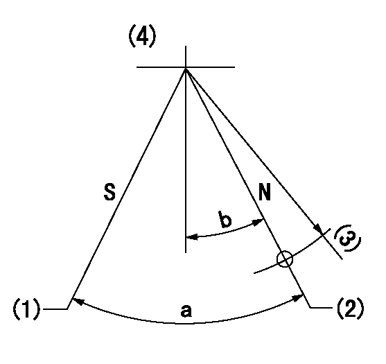
N:Pump normal
S:Stop the pump.
(1)Rack position = aa
(2)Rack position bb
(3)R = cc
(4)Adjust after setting excess fuel lever.
----------
aa=1+0.5mm bb=R2(12.5)+0.2mm cc=50mm
----------
a=32.5deg+-5deg b=30.5deg+-5deg
----------
aa=1+0.5mm bb=R2(12.5)+0.2mm cc=50mm
----------
a=32.5deg+-5deg b=30.5deg+-5deg
0000001101
N:Normal
B:When boosted
(1)Rack position = aa
----------
aa=13mm
----------
a=(18deg) b=(32deg)
----------
aa=13mm
----------
a=(18deg) b=(32deg)
0000001501 RACK SENSOR

V1:Supply voltage
V2f:Full side output voltage
V2i:Idle side output voltage
(A) Black
(B) Yellow
(C) Red
(D) Trimmer
(E): Shaft
(F) Nut
(G) Load lever
1. Load sensor adjustment
(1)Connect as shown in the above diagram and apply supply voltage V1.
(2)Hold the load lever (G) against the full side.
(3)Turn the shaft so that the voltage between (A) and (B) is V2.
(4)Hold the load lever (G) against the idle side.
(5)Adjust (D) so that the voltage between (A) and (B) is V2i.
(6)Repeat the above adjustments.
(7)Tighten the nut (F) at the point satisfying the standards.
(8)Hold the load lever against the full side stopper and the idle side stopper.
(9)At this time, confirm that the full side output voltage is V2f and the idle side output voltage is V2i.
----------
V1= 5+-0.02V V2f=0.3+0.03V V2i=2.2-0.03V
----------
----------
V1= 5+-0.02V V2f=0.3+0.03V V2i=2.2-0.03V
----------
Timing setting

(1)Pump vertical direction
(2)Coupling's key groove position at No 1 cylinder's beginning of injection
(3)-
(4)-
----------
----------
a=(20deg)
----------
----------
a=(20deg)
Information:
There are two operation checks that are fast and need no special equipment. One check is the PULL-DOWN RPM CHECK to see if the BrakeSaver can give full braking force. The other check is the KLUNK CHECK to see if the valve spool in the BrakeSaver control valve has free movement. These two checks give an approximate indication that the BrakeSaver has the correct operation.Pull-Down RPM Check
The engine must give rated horsepower for this test to have accuracy.1. Actuate the brakes, put the transmission in NEUTRAL and operate the engine at high idle rpm (accelerator pedal all the way down).2. Make a record of the engine rpm.3. Put the BrakeSaver control to the full ON position.4. Make a record of the engine rpm with the BrakeSaver full on.5. The engine rpm with the BrakeSaver full on must be 150 25 rpm less than the engine rpm with the BrakeSaver off. If the difference in rpm is less than 125 rpm, the BrakeSaver is not giving full braking force. If the difference in rpm is more than 175 rpm, check the air pressure to the BrakeSaver control valve. The air pressure must not be more than 345 kPa (50 psi).
Do not run the engine at high idle rpm with the BrakeSaver ON for more than 15 seconds at a time. Let the engine run a low idle with the BrakeSaver off for five minutes to keep from getting the engine cooling system too hot.
Klunk Check (check for free movement of the valve spool)
1. Run the engine until the truck air system is at its maximum pressure and then stop the engine.2. Put the BrakeSaver in the full ON position before the air pressure in the truck air system gets below 480 kPa (70 psi).3. Put the BrakeSaver in the OFF position. A noise ("klunk") must be heard at the BrakeSaver control valve as the valve spool hits the cover at the air inlet end of the control valve.4. If the noise is not heard at the BrakeSaver control valve, remove and disassemble the control valve. Inspect the valve for: a. A damaged valve body.b. Damaged or worn springs in the valve spool.c. Damaged or worn valve spool.d. Damaged or worn O-ring seals or diaphragm in the control valve.e. Closed holes (small holes to feel pressure) in the side of the valve spool.For specific problems, make reference to the PROBLEM LIST below.Problem List
1. BrakeSaver does not give full braking force with the mode selector switch in the MANUAL position.2. BrakeSaver does not give full braking force with the mode selector switch in the AUTOMATIC-MANUAL position.3. BrakeSaver Oil temperature is too high.4. BrakeSaver does not turn OFF or become empty.5. Oil leakage from the flywheel housing.6. Oil leakage from the clutch housing or transmission.
Gauge Holes For Troubleshooting
(1) Oil pressure from the BrakeSaver. (2) Oil pressure from the engine. (3) Oil pressure to the BrakeSaver. (4) Test point for BrakeSaver oil temperature. (5) Oil pressure to the engine. (6) Air pressure
Have questions with 106671-0245?
Group cross 106671-0245 ZEXEL
Nissan-Diesel
106671-0245
INJECTION-PUMP ASSEMBLY