Information injection-pump assembly
ZEXEL
106671-0212
1066710212
Rating:
Service parts 106671-0212 INJECTION-PUMP ASSEMBLY:
1.
_
5.
AUTOM. ADVANCE MECHANIS
7.
COUPLING PLATE
8.
_
9.
_
11.
Nozzle and Holder
16600-96514
12.
Open Pre:MPa(Kqf/cm2)
17.7{180}/22.6{230}

15.
NOZZLE SET
Include in #1:
106671-0212
as INJECTION-PUMP ASSEMBLY
Cross reference number
ZEXEL
106671-0212
1066710212
Zexel num
Bosch num
Firm num
Name
Calibration Data:
Adjustment conditions
Test oil
1404 Test oil ISO4113 or {SAEJ967d}
1404 Test oil ISO4113 or {SAEJ967d}
Test oil temperature
degC
40
40
45
Nozzle and nozzle holder
105780-8140
Bosch type code
EF8511/9A
Nozzle
105780-0000
Bosch type code
DN12SD12T
Nozzle holder
105780-2080
Bosch type code
EF8511/9
Opening pressure
MPa
17.2
Opening pressure
kgf/cm2
175
Injection pipe
Outer diameter - inner diameter - length (mm) mm 8-3-600
Outer diameter - inner diameter - length (mm) mm 8-3-600
Overflow valve opening pressure
kPa
157
123
191
Overflow valve opening pressure
kgf/cm2
1.6
1.25
1.95
Tester oil delivery pressure
kPa
157
157
157
Tester oil delivery pressure
kgf/cm2
1.6
1.6
1.6
Direction of rotation (viewed from drive side)
Right R
Right R
Injection timing adjustment
Direction of rotation (viewed from drive side)
Right R
Right R
Injection order
1-4-2-6-
3-5
Pre-stroke
mm
3.65
3.6
3.7
Beginning of injection position
Drive side NO.1
Drive side NO.1
Difference between angles 1
Cal 1-4 deg. 60 59.5 60.5
Cal 1-4 deg. 60 59.5 60.5
Difference between angles 2
Cyl.1-2 deg. 120 119.5 120.5
Cyl.1-2 deg. 120 119.5 120.5
Difference between angles 3
Cal 1-6 deg. 180 179.5 180.5
Cal 1-6 deg. 180 179.5 180.5
Difference between angles 4
Cal 1-3 deg. 240 239.5 240.5
Cal 1-3 deg. 240 239.5 240.5
Difference between angles 5
Cal 1-5 deg. 300 299.5 300.5
Cal 1-5 deg. 300 299.5 300.5
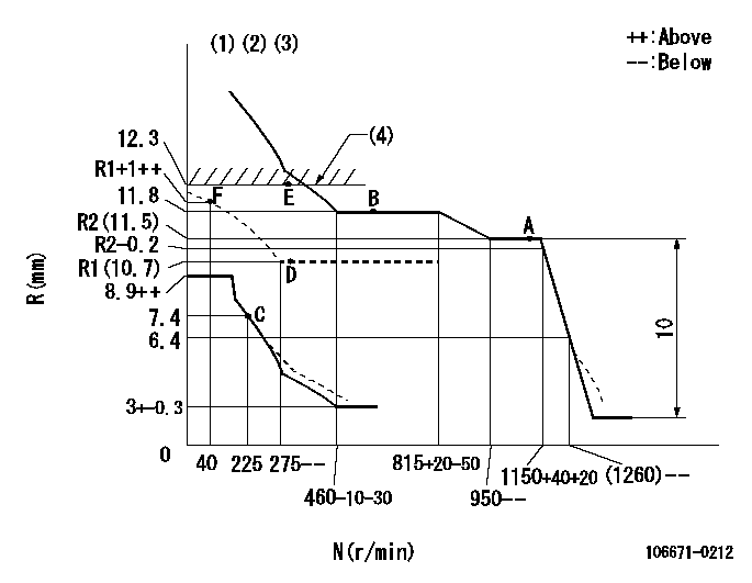
Injection quantity adjustment
Adjusting point
A
Rack position
R2(11.5)
Pump speed
r/min
1100
1100
1100
Average injection quantity
mm3/st.
153.8
149.8
157.8
Max. variation between cylinders
%
0
-5
5
Fixing the lever
*
Boost pressure
kPa
30.7
30.7
Boost pressure
mmHg
230
230
Injection quantity adjustment_02
Adjusting point
B
Rack position
11.8
Pump speed
r/min
600
600
600
Average injection quantity
mm3/st.
161.7
159.7
163.7
Max. variation between cylinders
%
0
-4
4
Basic
*
Fixing the lever
*
Boost pressure
kPa
30.7
30.7
Boost pressure
mmHg
230
230
Injection quantity adjustment_03
Adjusting point
C
Rack position
7.4+-0.5
Pump speed
r/min
225
225
225
Average injection quantity
mm3/st.
10.1
9.1
11.1
Max. variation between cylinders
%
0
-10
10
Fixing the rack
*
Boost pressure
kPa
0
0
0
Boost pressure
mmHg
0
0
0
Injection quantity adjustment_04
Adjusting point
D
Rack position
R1(10.7)
Pump speed
r/min
300
300
300
Average injection quantity
mm3/st.
120.6
118.6
122.6
Fixing the lever
*
Boost pressure
kPa
0
0
0
Boost pressure
mmHg
0
0
0
Injection quantity adjustment_05
Adjusting point
E
Rack position
12.3
Pump speed
r/min
300
300
300
Average injection quantity
mm3/st.
171.1
166.1
176.1
Fixing the lever
*
Rack limit
*
Boost compensator adjustment
Pump speed
r/min
300
300
300
Rack position
R1(10.7)
Boost pressure
kPa
4
Boost pressure
mmHg
30
Boost compensator adjustment_02
Pump speed
r/min
300
300
300
Rack position
12.3
Boost pressure
kPa
17.3
17.3
17.3
Boost pressure
mmHg
130
130
130
Test data Ex:
Governor adjustment
N:Pump speed
R:Rack position (mm)
(1)Lever ratio: RT
(2)Target shim dimension: TH
(3)Damper spring setting: DL
(4)Rack limit using stop lever
----------
RT=1 TH=2mm DL=6.4-0.2mm
----------
----------
RT=1 TH=2mm DL=6.4-0.2mm
----------
Timer adjustment

(1)Adjusting range
(2)Step response time
(N): Speed of the pump
(L): Load
(theta) Advance angle
(Srd1) Step response time 1
(Srd2) Step response time 2
1. Adjusting conditions for the variable timer
(1)Adjust the clearance between the pickup and the protrusion to L.
----------
L=1-0.2mm N2=800r/min C2=(6.5)deg t1=2--sec. t2=2--sec.
----------
N1=1250++r/min P1=0kPa(0kgf/cm2) P2=392kPa(4kgf/cm2) C1=6.5+-0.3deg R01=0/4load R02=4/4load
----------
L=1-0.2mm N2=800r/min C2=(6.5)deg t1=2--sec. t2=2--sec.
----------
N1=1250++r/min P1=0kPa(0kgf/cm2) P2=392kPa(4kgf/cm2) C1=6.5+-0.3deg R01=0/4load R02=4/4load
Speed control lever angle
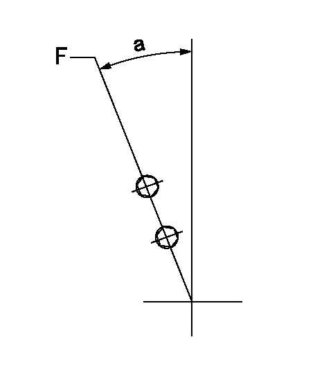
F:Full speed
----------
----------
a=31deg+-5deg
----------
----------
a=31deg+-5deg
0000000901
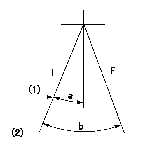
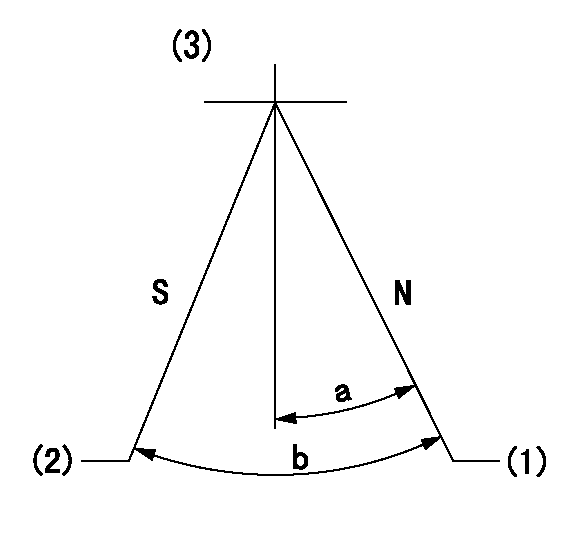
F:Full load
I:Idle
(1)Stopper bolt setting
(2)At center of threaded hole above R = aa
----------
aa=17mm
----------
a=22deg+-5deg b=32.5deg+-3deg
----------
aa=17mm
----------
a=22deg+-5deg b=32.5deg+-3deg
Stop lever angle
N:Pump normal
S:Stop the pump.
(1)Rack position = aa
(2)Rack position bb
(3)Adjust after setting excess fuel lever.
----------
aa=12.3mm bb=1+0.5mm
----------
a=29.5deg+-5deg b=31.5deg+-5deg
----------
aa=12.3mm bb=1+0.5mm
----------
a=29.5deg+-5deg b=31.5deg+-5deg
0000001101
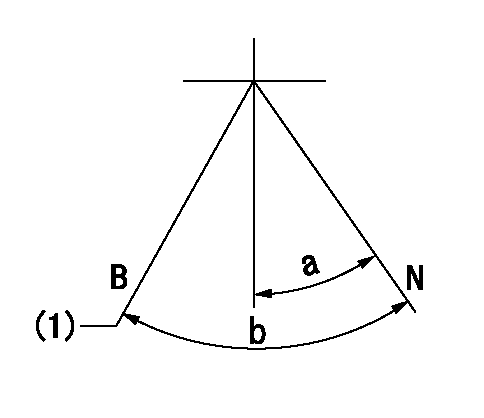
N:Normal
B:When boosted
(1)Rack position = aa
----------
aa=13mm
----------
a=(18deg) b=(32deg)
----------
aa=13mm
----------
a=(18deg) b=(32deg)
0000001501 RACK SENSOR

V1:Supply voltage
V2f:Full side output voltage
V2i:Idle side output voltage
(A) Black
(B) Yellow
(C) Red
(D) Trimmer
(E): Shaft
(F) Nut
(G) Load lever
1. Load sensor adjustment
(1)Connect as shown in the above diagram and apply supply voltage V1.
(2)Hold the load lever (G) against the full side.
(3)Turn the shaft so that the voltage between (A) and (B) is V2.
(4)Hold the load lever (G) against the idle side.
(5)Adjust (D) so that the voltage between (A) and (B) is V2i.
(6)Repeat the above adjustments.
(7)Tighten the nut (F) at the point satisfying the standards.
(8)Hold the load lever against the full side stopper and the idle side stopper.
(9)At this time, confirm that the full side output voltage is V2f and the idle side output voltage is V2i.
----------
V1= 5+-0.02V V2f=0.3+0.03V V2i=2.2-0.03V
----------
----------
V1= 5+-0.02V V2f=0.3+0.03V V2i=2.2-0.03V
----------
Timing setting

(1)Pump vertical direction
(2)Coupling's key groove position at No 1 cylinder's beginning of injection
(3)-
(4)-
----------
----------
a=(20deg)
----------
----------
a=(20deg)
Information:
March 8, 2005
(Revised July 2005)
U-76
A-57
O-65
TT-3
Afterfailure only PRODUCT SUPPORT PROGRAM FOR INSTALLINGINJECTOR SLEEVE KITS IN CERTAIN C11 AND C13 TRUCK ENGINES
1713 PS50933
This Program can only be administeredafter a failure occurs. The decision whether to apply the Program is madeby the dealer. When reporting the repair, use "PS50933" as the Part numberand "7755" as the Group Number. Use "96" as the Warranty Claim DescriptionCode and use "Z" as the SIMS Description Code. The information supplied in this serviceletter may not be valid after the termination date of this program. Donot perform the work outlined in this Service Letter after the terminationdate without first contacting your Caterpillar product analyst. This Revised Service Letter replacesthe March 8, 2005 Service Letter. Changes have been made to the ServiceClaim Allowance.TERMINATION DATE
March 31, 2007PROBLEM
This letter will address the repair proceduresand inspection guidelines for fuel in coolant failures in certain C11 andC13 ACERT engines.AFFECTED PRODUCT
Model Identification Number
C11 KCA1-2365
C13 KCB1-14118PARTS NEEDED
Qty
Part Number
Description
1 2638162 INJECTOR KITACTION REQUIRED
If a failure of an injector sleeve isdiscovered replace all 6 injector sleeves. Follow special instruction REHS2410,field installation of the 263-8162 injector sleeve kit. After the repairof the injector sleeves is completed, inspect the following components:pre-cooler hoses, coolant diverter valve, and thermostat(s). Replace anycomponents that show signs of deformity or swelling due to exposure tofuel.SERVICE CLAIM ALLOWANCES
SMCS Code Description SC MC CV CO
1240-030 Test 0.5 0.5 0.5 0.5
1240-074 Wash 0.3 0.3 0.3 0.3
1100-035 Troubleshoot 1.0 1.0 1.0 1.0
1290-010-S Remove and Install Unit Injector,Set (all) 5.2 5.0 5.0 5.1
1713-010-S Remove and Install Unit InjectorSleeve, Set (all) 2.0 2.0 2.0 2.0
1350-046-ES Flush Engine Cooling System 1.3 1.3 1.3 1.3
Note: If equippedwith a head-mounted radiator bracket, claim code (1353-010-BK).
Note: If R&I ofair cleaner housing is required, claim code (1051-010).PARTS DISPOSITION
Handle the parts in accordance with your WarrantyBulletin on warranty parts handling.