Information injection-pump assembly
ZEXEL
106671-0150
1066710150

Rating:
Service parts 106671-0150 INJECTION-PUMP ASSEMBLY:
1.
_
7.
COUPLING PLATE
8.
_
9.
_
11.
Nozzle and Holder
16600-96514
12.
Open Pre:MPa(Kqf/cm2)
17.7{180}/22.6{230}

15.
NOZZLE SET
Include in #1:
106671-0150
as INJECTION-PUMP ASSEMBLY
Cross reference number
ZEXEL
106671-0150
1066710150
Zexel num
Bosch num
Firm num
Name
Calibration Data:
Adjustment conditions
Test oil
1404 Test oil ISO4113 or {SAEJ967d}
1404 Test oil ISO4113 or {SAEJ967d}
Test oil temperature
degC
40
40
45
Nozzle and nozzle holder
105780-8140
Bosch type code
EF8511/9A
Nozzle
105780-0000
Bosch type code
DN12SD12T
Nozzle holder
105780-2080
Bosch type code
EF8511/9
Opening pressure
MPa
17.2
Opening pressure
kgf/cm2
175
Injection pipe
Outer diameter - inner diameter - length (mm) mm 8-3-600
Outer diameter - inner diameter - length (mm) mm 8-3-600
Overflow valve opening pressure
kPa
157
123
191
Overflow valve opening pressure
kgf/cm2
1.6
1.25
1.95
Tester oil delivery pressure
kPa
157
157
157
Tester oil delivery pressure
kgf/cm2
1.6
1.6
1.6
Direction of rotation (viewed from drive side)
Right R
Right R
Injection timing adjustment
Direction of rotation (viewed from drive side)
Right R
Right R
Injection order
1-4-2-6-
3-5
Pre-stroke
mm
3.65
3.6
3.7
Beginning of injection position
Drive side NO.1
Drive side NO.1
Difference between angles 1
Cal 1-4 deg. 60 59.5 60.5
Cal 1-4 deg. 60 59.5 60.5
Difference between angles 2
Cyl.1-2 deg. 120 119.5 120.5
Cyl.1-2 deg. 120 119.5 120.5
Difference between angles 3
Cal 1-6 deg. 180 179.5 180.5
Cal 1-6 deg. 180 179.5 180.5
Difference between angles 4
Cal 1-3 deg. 240 239.5 240.5
Cal 1-3 deg. 240 239.5 240.5
Difference between angles 5
Cal 1-5 deg. 300 299.5 300.5
Cal 1-5 deg. 300 299.5 300.5
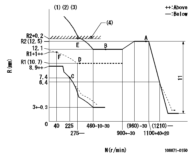
Injection quantity adjustment
Adjusting point
A
Rack position
R2(12.5)
Pump speed
r/min
1100
1100
1100
Average injection quantity
mm3/st.
185.6
181.6
189.6
Max. variation between cylinders
%
0
-5
5
Fixing the lever
*
Boost pressure
kPa
33.3
33.3
Boost pressure
mmHg
250
250
Injection quantity adjustment_02
Adjusting point
B
Rack position
12.1
Pump speed
r/min
600
600
600
Average injection quantity
mm3/st.
171
169
173
Max. variation between cylinders
%
0
-4
4
Basic
*
Fixing the lever
*
Boost pressure
kPa
33.3
33.3
Boost pressure
mmHg
250
250
Injection quantity adjustment_03
Adjusting point
C
Rack position
7.4+-0.5
Pump speed
r/min
225
225
225
Average injection quantity
mm3/st.
10.1
9.1
11.1
Max. variation between cylinders
%
0
-10
10
Fixing the rack
*
Boost pressure
kPa
0
0
0
Boost pressure
mmHg
0
0
0
Injection quantity adjustment_04
Adjusting point
D
Rack position
R1(10.7)
Pump speed
r/min
300
300
300
Average injection quantity
mm3/st.
120.6
118.6
122.6
Fixing the lever
*
Boost pressure
kPa
0
0
0
Boost pressure
mmHg
0
0
0
Injection quantity adjustment_05
Adjusting point
E
Rack position
R2+0.2
Pump speed
r/min
300
300
300
Average injection quantity
mm3/st.
186.3
176.3
196.3
Fixing the lever
*
Rack limit
*
Boost compensator adjustment
Pump speed
r/min
300
300
300
Rack position
R1(10.7)
Boost pressure
kPa
4
Boost pressure
mmHg
30
Boost compensator adjustment_02
Pump speed
r/min
300
300
300
Rack position
R2+0.2
Boost pressure
kPa
20
20
20
Boost pressure
mmHg
150
150
150
Test data Ex:
Governor adjustment
N:Pump speed
R:Rack position (mm)
(1)Lever ratio: RT
(2)Target shim dimension: TH
(3)Damper spring setting: DL
(4)Rack limit using stop lever
----------
RT=1 TH=2.7mm DL=6.4-0.2mm
----------
----------
RT=1 TH=2.7mm DL=6.4-0.2mm
----------
Timer adjustment

(1)Adjusting range
(2)Step response time
(N): Speed of the pump
(L): Load
(theta) Advance angle
(Srd1) Step response time 1
(Srd2) Step response time 2
1. Adjusting conditions for the variable timer
(1)Adjust the clearance between the pickup and the protrusion to L.
----------
L=1-0.2mm N2=800r/min C2=(6.5)deg t1=2--sec. t2=2--sec.
----------
N1=1250++r/min P1=0kPa(0kgf/cm2) P2=392kPa(4kgf/cm2) C1=6.5+-0.5deg R01=0/4load R02=4/4load
----------
L=1-0.2mm N2=800r/min C2=(6.5)deg t1=2--sec. t2=2--sec.
----------
N1=1250++r/min P1=0kPa(0kgf/cm2) P2=392kPa(4kgf/cm2) C1=6.5+-0.5deg R01=0/4load R02=4/4load
Speed control lever angle

F:Full speed
----------
----------
a=30deg+-5deg
----------
----------
a=30deg+-5deg
0000000901
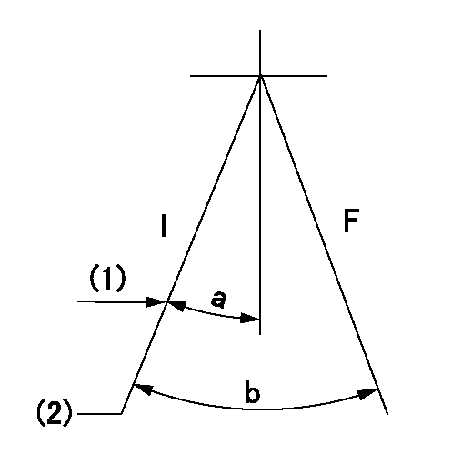
F:Full load
I:Idle
(1)Stopper bolt setting
(2)At center of threaded hole above R = aa
----------
aa=17mm
----------
a=22deg+-5deg b=33deg+-3deg
----------
aa=17mm
----------
a=22deg+-5deg b=33deg+-3deg
Stop lever angle
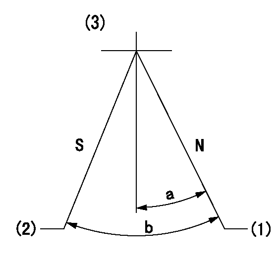
N:Pump normal
S:Stop the pump.
(1)Rack position = aa
(2)Rack position bb, pump speed cc
(3)Adjust after setting excess fuel lever.
----------
aa=R2(12.5)+0.2mm bb=1+0.5mm cc=0r/min
----------
a=20.5deg+-5deg b=33.5deg+-5deg
----------
aa=R2(12.5)+0.2mm bb=1+0.5mm cc=0r/min
----------
a=20.5deg+-5deg b=33.5deg+-5deg
0000001101
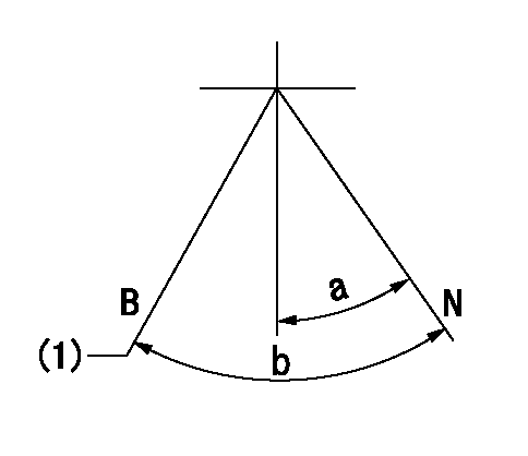
N:Normal
B:When boosted
(1)Rack position = aa
----------
aa=13mm
----------
a=(18deg) b=(32deg)
----------
aa=13mm
----------
a=(18deg) b=(32deg)
0000001501 RACK SENSOR

V1:Supply voltage
V2f:Full side output voltage
V2i:Idle side output voltage
(A) Black
(B) Yellow
(C) Red
(D) Trimmer
(E): Shaft
(F) Nut
(G) Load lever
1. Load sensor adjustment
(1)Connect as shown in the above diagram and apply supply voltage V1.
(2)Hold the load lever (G) against the full side.
(3)Turn the shaft so that the voltage between (A) and (B) is V2.
(4)Hold the load lever (G) against the idle side.
(5)Adjust (D) so that the voltage between (A) and (B) is V2i.
(6)Repeat the above adjustments.
(7)Tighten the nut (F) at the point satisfying the standards.
(8)Hold the load lever against the full side stopper and the idle side stopper.
(9)At this time, confirm that the full side output voltage is V2f and the idle side output voltage is V2i.
----------
V1= 5+-0.02V V2f=0.3+0.03V V2i=2.2-0.03V
----------
----------
V1= 5+-0.02V V2f=0.3+0.03V V2i=2.2-0.03V
----------
Timing setting

(1)Pump vertical direction
(2)Coupling's key groove position at No 1 cylinder's beginning of injection
(3)-
(4)-
----------
----------
a=(20deg)
----------
----------
a=(20deg)
Information:
Product smu Caterpillar Dealer Suggested Customer Suggested
Parts Labor Hrs Parts Labor Hrs Parts Labor Hrs
0-4000 100% 7.0 0 0 0 0
4001-8000 50% 3.5 0 0 50% 0
This is a 7.0?hr job.PARTS DISPOSITION
Handle the parts in accordance with your WarrantyBulletin on warranty parts handling.Attach. (1-Rework Procedure)Rework Procedure
The two tests below provide the appropriateinjector troubleshooting and repair steps for injector updates.Test 1: Use "Test for CylinderCutout" to determine if individual injector replacements (using originalinjector part) are needed.Test 2: Use "Test for Leakagefrom Poppet Valve" to determine if full injector sets (using new injectorparts and a software change from the table) are appropriate for repair.Test for Cylinder Cutout:
Warm the engine out of Cold Mode.
Connect Caterpillar Electronic Technician (ET)to the engine while the engine is running.
Ensure that the engine speed is 1200 rpm +/- 125rpm. An extremely rough running engine will need to be diagnosed by othermethods.
Cut out one bank of cylinders.
Engine rpm and the fuel positionon the ET screen at that time.
Cut out one of the remaining cylinders from thecylinder bank that is running. Allow the engine to stabilize and note thefuel position.
Give power back to that cylinder. Allow the engineto stabilize and note the fuel position.
Repeat steps 5 through 6 until the cylinder bankhas been completely checked.
Power all cylinders. Allow the engine to stabilize.
Cut out the other cylinder bank and repeat steps5 through 8.
Repeat steps 4 through 9 with the engine at 2000rpm.
Compare the results from the fuel position fromeach cylinder.
If the cylinder was cut out and the fuel positiondid not change, the cylinder may not have producing power. This cylinderwould be suspect.
When you are finished with the test, decreaseengine rpm to low idle and shut the engine off.
Replace any suspect injector with a similar originalinjector. Install new seals for the injector and the jumper tube duringthis repair. The injector repair procedure is found in Special InstructionREHS0116.
It is also possible that multiple injectors arefunctioning improperly. Complete "Test for Leakage from Poppet Valve" inorder to evaluate potential excessive injector leakage and need for fuelsystem conversion.Test for Leakage from Poppet Valve:
Warm engine out of Cold Mode to normaloperating temperature.
Turn off the engine.
Remove the valve cover bolts in preparation toobserve the injectors. Leave covers in place.
!Personal injury can result from hot oil and components. Do not allowhot oil or components to contact skin.
Restart the engine and run at low idle with noload.
Use the ET service tool in order to perform theoverride test for the injection actuation system. Increase injection actuationpressure to the maximum value.
Observe all of the injectors under each valvecover for leakage at the spill port. A small amount of dripping is acceptable.However, a continuous stream of oil is an indication of excessive leakageof the poppet valve. Only leaks at the spill port are an indication ofexcessive poppet valve leakage.
If multiple injectors are discovered with excessiveleakage from the poppet valve, update the full set of injectors and softwarewith the new version given in this Service Letter. Install new seals forthe injector and the jumper tube during this repair. The injector repairprocedure can be found in Special Instruction REHS0116. The old softwarepart number should be documented for potential future reference.
Before proceeding with updating