Information injection-pump assembly
BOSCH
9 400 616 643
9400616643
ZEXEL
106662-4160
1066624160
DAIHATSU
M121610140A
m121610140a
Rating:
Cross reference number
BOSCH
9 400 616 643
9400616643
ZEXEL
106662-4160
1066624160
DAIHATSU
M121610140A
m121610140a
Zexel num
Bosch num
Firm num
Name
106662-4160
9 400 616 643
M121610140A DAIHATSU
INJECTION-PUMP ASSEMBLY
M2 K 14CA INJECTION PUMP ASSY PE6P,6PD PE
M2 K 14CA INJECTION PUMP ASSY PE6P,6PD PE
Calibration Data:
Adjustment conditions
Test oil
1404 Test oil ISO4113 or {SAEJ967d}
1404 Test oil ISO4113 or {SAEJ967d}
Test oil temperature
degC
40
40
45
Nozzle and nozzle holder
105780-8130
Bosch type code
EFEP215A
Nozzle
105780-0050
Bosch type code
DN6TD119NP1T
Nozzle holder
105780-2090
Bosch type code
EFEP215
Opening pressure
MPa
17.2
Opening pressure
kgf/cm2
175
Injection pipe
Outer diameter - inner diameter - length (mm) mm 8-3-600
Outer diameter - inner diameter - length (mm) mm 8-3-600
Overflow valve
131424-1520
Overflow valve opening pressure
kPa
157
157
157
Overflow valve opening pressure
kgf/cm2
1.6
1.6
1.6
Tester oil delivery pressure
kPa
157
157
157
Tester oil delivery pressure
kgf/cm2
1.6
1.6
1.6
Direction of rotation (viewed from drive side)
Right R
Right R
Injection timing adjustment
Direction of rotation (viewed from drive side)
Right R
Right R
Injection order
1-4-2-6-
3-5
Pre-stroke
mm
2.05
2
2.1
Beginning of injection position
Governor side NO.1
Governor side NO.1
Difference between angles 1
Cal 1-4 deg. 60 59.5 60.5
Cal 1-4 deg. 60 59.5 60.5
Difference between angles 2
Cyl.1-2 deg. 120 119.5 120.5
Cyl.1-2 deg. 120 119.5 120.5
Difference between angles 3
Cal 1-6 deg. 180 179.5 180.5
Cal 1-6 deg. 180 179.5 180.5
Difference between angles 4
Cal 1-3 deg. 240 239.5 240.5
Cal 1-3 deg. 240 239.5 240.5
Difference between angles 5
Cal 1-5 deg. 300 299.5 300.5
Cal 1-5 deg. 300 299.5 300.5
Injection quantity adjustment
Adjusting point
A
Rack position
10.8
Pump speed
r/min
750
750
750
Average injection quantity
mm3/st.
175
170.2
179.8
Max. variation between cylinders
%
0
-3
3
Basic
*
Fixing the lever
*
Injection quantity adjustment_02
Adjusting point
B
Rack position
5.5+-0.5
Pump speed
r/min
300
300
300
Average injection quantity
mm3/st.
25
22.5
27.5
Max. variation between cylinders
%
0
-10
10
Fixing the rack
*
Test data Ex:
Governor adjustment
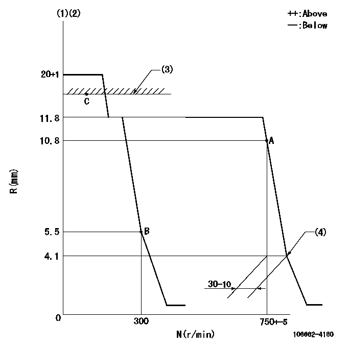
N:Pump speed
R:Rack position (mm)
(1)Target notch: K
(2)Delivered with idle spring not operating.
(3)RACK LIMIT: RAL
(4)Idle sub spring setting: L1.
----------
K=9 RAL=14+-0.5mm L1=4.1-0.5mm
----------
----------
K=9 RAL=14+-0.5mm L1=4.1-0.5mm
----------
Speed control lever angle
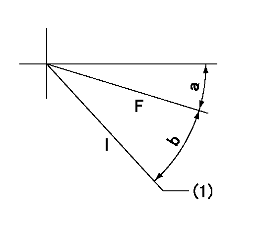
F:Full speed
I:Idle
(1)Stopper bolt setting
----------
----------
a=3deg+-5deg b=21.5deg+-5deg
----------
----------
a=3deg+-5deg b=21.5deg+-5deg
Stop lever angle
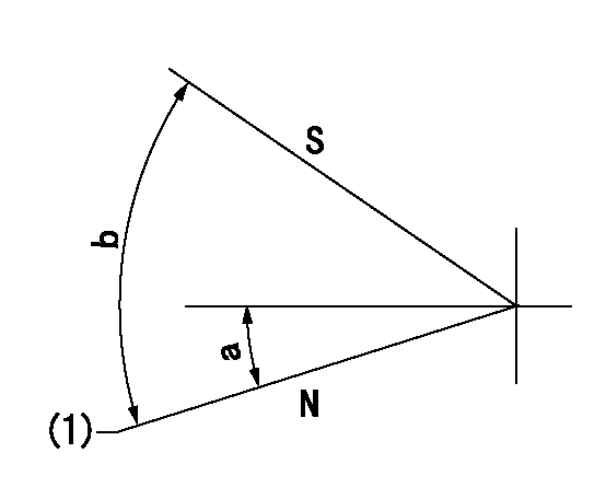
N:Pump normal
S:Stop the pump.
(1)Normal
----------
----------
a=(11deg) b=(53deg)
----------
----------
a=(11deg) b=(53deg)
Information:
Caterpillar: Confidential Yellow
PSP FOR THE USE OF TWO CLAMPS TO HOLD THE BODY AND FUEL NOZZLE IN POSITION ON 3406, 3408 AND 3412 ENGINES - MAILED WORLDWIDE EXC EPT CANADA, BRAZIL & CACO
The information supplied in this service letter may not be valid after the termination date of this program. Do not perform the work outlined in this Service Letter after the termination date without first contacting your Caterpillar product analyst.
PRODUCT SUPPORT PROGRAM FOR THE USE OF TWO CLAMPS TO HOLD THE BODY AND FUEL NOZZLE IN POSITION ON 3406, 3408 AND 3412 ENGINES, 1252, PS4019 U-74 AU-59 E-47 O-45 TT-12 TA-6 TM-6 This Program can be administered either before or after a failure. In either case the warranty allowances will be the same and contingent damage will not be allowed. The decision whether to apply the Program is made by the dealer. When reporting the repair use "PS4019" as Part Number and "7755" as Group Number. Although products in the field are to be administered as described above, dealers should rework parts stock immediately. Termination Date
September 30, 1986.
Problem
Engines equipped with 4W5719 (3406) or 4W5733 (3408, 3412) Adapter Assemblies use one 4W5717 Clamp to hold the body and fuel nozzle in position. See the Illustration. These adapter assemblies are also used in 0R0977 (3406) 0R0980 (3408) and 0R2659 (3412) Remanufactured Head Assemblies. One clamp does not provide enough force to hold the body and fuel nozzle tight. This permits fuel to leak past the internal parts of the nozzle and cause the nozzle case to bulge or split. This program provides for an additional clamp and bolts to be used with these adapter assemblies. (SEE ILLUSTRATION)
Affected Product
1/850907/01/002
Parts Needed
1-4W5717 Clamp and 2-5P6900 Bolts for each adapter assembly.
Action Required
The new parts should be installed on cylinder heads in parts stock immediately. Only cylinder heads received before this Service Letter need to be checked. The new parts should be installed on products in the field only when the valve cover has been removed for some other repair or inspection. Install the new clamp and bolts 180 deg. from the existing clamp and bolts. Tighten the bolts for the new clamp to 31 +/- 7 N X m (23 +/- 5 lb ft). Check to make sure the bolts for the existing clamp are tightened to the same torque. Then check the torque on the bolts for the new clamp. (SEE ILLUSTRATION)
Parts Disposition
Not applicable.
Have questions with 106662-4160?
Group cross 106662-4160 ZEXEL
Daihatsu
Yanmar
Yanmar
Daihatsu
106662-4160
9 400 616 643
M121610140A
INJECTION-PUMP ASSEMBLY
M2
M2