Information injection-pump assembly
ZEXEL
106661-5570
1066615570

Rating:
Service parts 106661-5570 INJECTION-PUMP ASSEMBLY:
1.
_
7.
COUPLING PLATE
8.
_
9.
_
11.
Nozzle and Holder
16600-96510
12.
Open Pre:MPa(Kqf/cm2)
19.6{200}
15.
NOZZLE SET
Include in #1:
106661-5570
as INJECTION-PUMP ASSEMBLY
Cross reference number
ZEXEL
106661-5570
1066615570
Zexel num
Bosch num
Firm num
Name
106661-5570
INJECTION-PUMP ASSEMBLY
Calibration Data:
Adjustment conditions
Test oil
1404 Test oil ISO4113 or {SAEJ967d}
1404 Test oil ISO4113 or {SAEJ967d}
Test oil temperature
degC
40
40
45
Nozzle and nozzle holder
105780-8140
Bosch type code
EF8511/9A
Nozzle
105780-0000
Bosch type code
DN12SD12T
Nozzle holder
105780-2080
Bosch type code
EF8511/9
Opening pressure
MPa
17.2
Opening pressure
kgf/cm2
175
Injection pipe
Outer diameter - inner diameter - length (mm) mm 8-3-600
Outer diameter - inner diameter - length (mm) mm 8-3-600
Overflow valve
132424-0620
Overflow valve opening pressure
kPa
157
123
191
Overflow valve opening pressure
kgf/cm2
1.6
1.25
1.95
Tester oil delivery pressure
kPa
157
157
157
Tester oil delivery pressure
kgf/cm2
1.6
1.6
1.6
Direction of rotation (viewed from drive side)
Right R
Right R
Injection timing adjustment
Direction of rotation (viewed from drive side)
Right R
Right R
Injection order
1-4-2-6-
3-5
Pre-stroke
mm
3.65
3.6
3.7
Beginning of injection position
Drive side NO.1
Drive side NO.1
Difference between angles 1
Cal 1-4 deg. 60 59.5 60.5
Cal 1-4 deg. 60 59.5 60.5
Difference between angles 2
Cyl.1-2 deg. 120 119.5 120.5
Cyl.1-2 deg. 120 119.5 120.5
Difference between angles 3
Cal 1-6 deg. 180 179.5 180.5
Cal 1-6 deg. 180 179.5 180.5
Difference between angles 4
Cal 1-3 deg. 240 239.5 240.5
Cal 1-3 deg. 240 239.5 240.5
Difference between angles 5
Cal 1-5 deg. 300 299.5 300.5
Cal 1-5 deg. 300 299.5 300.5
Injection quantity adjustment
Adjusting point
A
Rack position
9
Pump speed
r/min
600
600
600
Average injection quantity
mm3/st.
117.5
116.5
118.5
Max. variation between cylinders
%
0
-4
4
Basic
*
Fixing the lever
*
Injection quantity adjustment_02
Adjusting point
B
Rack position
5+-0.5
Pump speed
r/min
240
240
240
Average injection quantity
mm3/st.
9.5
8.2
10.8
Max. variation between cylinders
%
0
-10
10
Fixing the rack
*
Timer adjustment
Pump speed
r/min
950--
Advance angle
deg.
0
0
0
Remarks
Start
Start
Timer adjustment_02
Pump speed
r/min
900
Advance angle
deg.
0.5
Timer adjustment_03
Pump speed
r/min
1150
Advance angle
deg.
5
4.5
5.5
Remarks
Finish
Finish
Test data Ex:
Governor adjustment

N:Pump speed
R:Rack position (mm)
(1)Lever ratio: RT
(2)Target shim dimension: TH
(3)Tolerance for racks not indicated: +-0.05mm.
(4)Rack limit using the stop lever: R1
(5)Excess fuel setting for starting: SXL (N = N1)
(6)Damper spring setting
----------
RT=1 TH=2.3mm R1=10.8+0.2mm SXL9+0.2mm N1=430r/min
----------
----------
RT=1 TH=2.3mm R1=10.8+0.2mm SXL9+0.2mm N1=430r/min
----------
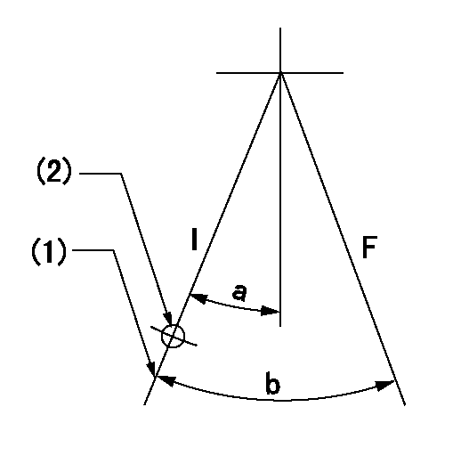
Speed control lever angle

F:Full speed
----------
----------
a=21deg+-5deg
----------
----------
a=21deg+-5deg
0000000901

F:Full load
I:Idle
(1)Stopper bolt setting
(2)At center of threaded hole above R = aa
----------
aa=17mm
----------
a=15deg+-5deg b=29deg+-3deg
----------
aa=17mm
----------
a=15deg+-5deg b=29deg+-3deg
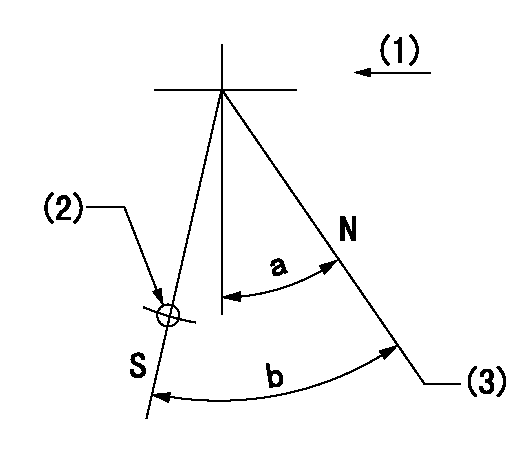
Stop lever angle

N:Pump normal
S:Stop the pump.
(1)Drive side
(2)Use the hole at R = aa
(3)Rack position bb
----------
aa=50mm bb=10.8+0.2mm
----------
a=26deg+-5deg b=28deg+-5deg
----------
aa=50mm bb=10.8+0.2mm
----------
a=26deg+-5deg b=28deg+-5deg
0000001501 ACS

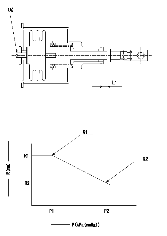
(A) Set screw
1. Aneroid compensator unit adjustment
Screw in (A) to obtain L1.
2. Adjustment following governor installation
(1)Set the speed of the pump to N1 r/min and fix the control lever at the full set position.
(2)Screw in the aneroid compensator to obtain the performance shown in the graph above.
----------
N1=600r/min L1=0.1~0.5mm
----------
R1=9mm R2=(8)mm P1=89+-2.7kPa(668+-20mmHg) P2=70+-0.7kPa(525+-5mmHg) Q1=117.5+-1cm3/1000st Q2=93.5+-2cm3/1000st
----------
N1=600r/min L1=0.1~0.5mm
----------
R1=9mm R2=(8)mm P1=89+-2.7kPa(668+-20mmHg) P2=70+-0.7kPa(525+-5mmHg) Q1=117.5+-1cm3/1000st Q2=93.5+-2cm3/1000st
Timing setting

(1)Pump vertical direction
(2)Coupling's key groove position at No 1 cylinder's beginning of injection
(3)-
(4)-
----------
----------
a=(30deg)
----------
----------
a=(30deg)
Information:
Introduction
The problem that is identified below does not have a known permanent solution. Until a permanent solution is known, use the solution that is identified below.Problem
Certain F2 series machines installed with Tier II or Tier III engines have reported low power from the engine. After troubleshooting, this low power has been diagnosed as being a faulty fuel injection pump.
Table 1
Required Parts
Part Number Part Name
10R-9707 Fuel Injection Pump Gp
10R-9715 Fuel Injection Pump Gp
20R-4832 Fuel Injection Pump Gp
236-8228 Fuel Injection Pump Gp
237-5213 Fuel Injection Pump Gp
248-2356 Fuel Injection Pump Gp
249-9226 Fuel Injection Pump Gp
266-3712 Fuel Injection Pump Gp
274-4962 Fuel Injection Pump Gp
326-8993 Fuel Injection Pump Gp
326-9147 Fuel Injection Pump Gp
368-5413 Fuel Injection Pump Gp
501-4461 Fuel Priming Pump and Primary Filter Gp Replace failed part with new part for your machine.Solution
Before replacing the fuel injection pump, the following actions can be performed to help ensure that the low-pressure fuel system is in good condition.
There is fuel in the fuel tank
Inspect the fuel filter for excess contamination, if necessary, install a new fuel filter
Check the fuel strainer in the bottom of the fuel tank is not blocked or damaged
Check that the fuel lift pump is delivering fuel to the fuel injection pump.
Check that the fuel tank has been regularly drained of any water contamination, and is clear of any debris that could be restricting the fuel flow. See the Operation and Maintenance Manual for correct maintenance practices.All these issues can cause low fuel pressure problems that could lead to thinking the fuel injection pump is faulty. If the low-pressure fuel system is working correctly, then inspect the fuel injection pump for water damage. Refer to special instruction REHS3767. If the fuel injection pump contains rust, then the root cause of the problem is water in the fuel supply.If necessary, a replacement fuel injection pump may be obtained. Refer to disassembly and assembly, "Fuel Injection Pump - Install" for the correct procedure to install a replacement fuel injection pump.Ensure that the fuel supply is clean and the fuel tank does not contain any water or contamination before installing a new Fuel Injection Pump. Also, replace the fuel filter. If a failure occurs, report the failure to the product group by completing a CPI Feedback Form at the Service Information Management System (SIMSi). Reference CPI 373959 and TIB , M0082583 in the form. The link to SIMSi can be found on the Caterpillar Service Information System (SIS).Note: For machines equipped with 501-4461 Fuel Priming Pump and Primary Filter Gp which has an extra water separation volume. Itis recommended to remove any aftermarket water separator.
Have questions with 106661-5570?
Group cross 106661-5570 ZEXEL
Nissan-Diesel
Nissan-Diesel
Nissan-Diesel
Nissan-Diesel
Nissan-Diesel
Nissan-Diesel
106661-5570
INJECTION-PUMP ASSEMBLY