Information injection-pump assembly
ZEXEL
106661-5550
1066615550
Rating:
Service parts 106661-5550 INJECTION-PUMP ASSEMBLY:
1.
_
7.
COUPLING PLATE
8.
_
9.
_
10.
NOZZLE AND HOLDER ASSY
11.
Nozzle and Holder
1660096508
12.
Open Pre:MPa(Kqf/cm2)
19.6{200}

15.
NOZZLE SET
Include in #1:
106661-5550
as INJECTION-PUMP ASSEMBLY
Cross reference number
ZEXEL
106661-5550
1066615550
Zexel num
Bosch num
Firm num
Name
106661-5550
INJECTION-PUMP ASSEMBLY
Calibration Data:
Adjustment conditions
Test oil
1404 Test oil ISO4113 or {SAEJ967d}
1404 Test oil ISO4113 or {SAEJ967d}
Test oil temperature
degC
40
40
45
Nozzle and nozzle holder
105780-8140
Bosch type code
EF8511/9A
Nozzle
105780-0000
Bosch type code
DN12SD12T
Nozzle holder
105780-2080
Bosch type code
EF8511/9
Opening pressure
MPa
17.2
Opening pressure
kgf/cm2
175
Injection pipe
Outer diameter - inner diameter - length (mm) mm 8-3-600
Outer diameter - inner diameter - length (mm) mm 8-3-600
Overflow valve
132424-0620
Overflow valve opening pressure
kPa
157
123
191
Overflow valve opening pressure
kgf/cm2
1.6
1.25
1.95
Tester oil delivery pressure
kPa
157
157
157
Tester oil delivery pressure
kgf/cm2
1.6
1.6
1.6
Direction of rotation (viewed from drive side)
Right R
Right R
Injection timing adjustment
Direction of rotation (viewed from drive side)
Right R
Right R
Injection order
1-4-2-6-
3-5
Pre-stroke
mm
3.65
3.6
3.7
Beginning of injection position
Drive side NO.1
Drive side NO.1
Difference between angles 1
Cal 1-4 deg. 60 59.5 60.5
Cal 1-4 deg. 60 59.5 60.5
Difference between angles 2
Cyl.1-2 deg. 120 119.5 120.5
Cyl.1-2 deg. 120 119.5 120.5
Difference between angles 3
Cal 1-6 deg. 180 179.5 180.5
Cal 1-6 deg. 180 179.5 180.5
Difference between angles 4
Cal 1-3 deg. 240 239.5 240.5
Cal 1-3 deg. 240 239.5 240.5
Difference between angles 5
Cal 1-5 deg. 300 299.5 300.5
Cal 1-5 deg. 300 299.5 300.5
Injection quantity adjustment
Adjusting point
A
Rack position
11.6
Pump speed
r/min
650
650
650
Average injection quantity
mm3/st.
114
113
115
Max. variation between cylinders
%
0
-4
4
Basic
*
Fixing the lever
*
Remarks
Rack limit using stop lever.
Rack limit using stop lever.
Injection quantity adjustment_02
Adjusting point
C
Rack position
7.8+-0.5
Pump speed
r/min
290
290
290
Average injection quantity
mm3/st.
10.5
9.2
11.8
Max. variation between cylinders
%
0
-10
10
Fixing the rack
*
Timer adjustment
Pump speed
r/min
-
Advance angle
deg.
0
0
0
Remarks
Measure speed (beginning of operation).
Measure speed (beginning of operation).
Timer adjustment_02
Pump speed
r/min
-
Advance angle
deg.
5
4.5
5.5
Remarks
Measure the actual speed, stop
Measure the actual speed, stop
Test data Ex:
Governor adjustment
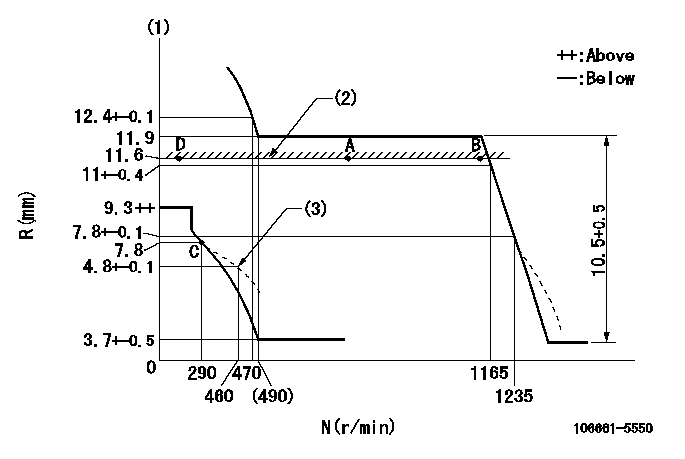
N:Pump speed
R:Rack position (mm)
(1)Tolerance for racks not indicated: +-0.05mm.
(2)Rack limit using stop lever
(3)Damper spring setting
----------
----------
----------
----------
Speed control lever angle

F:Full speed
----------
----------
a=20.5deg+-5deg
----------
----------
a=20.5deg+-5deg
0000000901
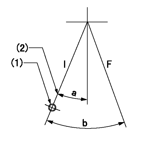
F:Full load
I:Idle
(1)At center of threaded hole above R = aa
(2)Stopper bolt setting
----------
aa=17mm
----------
a=15deg+-5deg b=30.5deg+-3deg
----------
aa=17mm
----------
a=15deg+-5deg b=30.5deg+-3deg
Stop lever angle
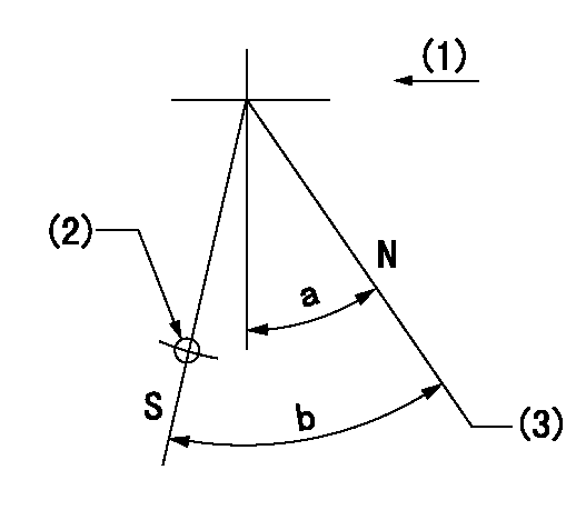
N:Pump normal
S:Stop the pump.
(1)Drive side
(2)Use the hole at R = aa
(3)Rack position bb
----------
aa=50mm bb=11.6mm
----------
a=28deg+-5deg b=30deg+-5deg
----------
aa=50mm bb=11.6mm
----------
a=28deg+-5deg b=30deg+-5deg
Timing setting

(1)Pump vertical direction
(2)Coupling's key groove position at No 1 cylinder's beginning of injection
(3)-
(4)-
----------
----------
a=(30deg)
----------
----------
a=(30deg)
Information:
Illustration 23. (2) 141-6737 Adjustable Microgauge.
(7) Top of the 3P-1542 Barrel. (8) 141-6727 Calibration Pump Assembly.1. Place the 141-6737 Adjustable Microgauge on top of the 3P-1542 Barrel of the 141-6727 Calibration Pump Assembly.2. When starting to torque 124-5932 Lever Assemblies, the difference between the face of the 141-6730 Plunger and the 2N-2658 Bolt is about 0.03 mm (.001 in). By setting the 141-6737 Adjustable Microgauge (2) on top of the 141-6727 Calibration Pump Assembly (8), the 141-6737 Plunger can be positioned 25.40 mm (.001 in) above the face of the 3P-1542 Barrel (7).
Illustration 24. (9) 2N-2658 Bolt. (10) 124-5940 Shutoff Lever.3. As the 2N-2658 Bolt (9) is torqued, the 141-6730 Plunger will move down flush with the 3P-1542 Barrel (7) or will be very close to being flush. The calibration can begin from this point. The 2N-2658 Bolts must freely turn in and out of the 124-5940 Shutoff Levers (10) because the calibration depends on where the head of the 2N-2658 Bolt (9) first begins to clamp the 124-5940 Shutoff Lever for the starting point of the calibration.End Play Adjustment
1. In order to save time, use two torque wrenches (color-coding is convenient for distinguishing between the two wrenches). Set one torque wrench to 1.7 N m (15 lb in) and the second torque wrench to N m (35 lb in).
Illustration 25. (1) 124-5941 Shaft. (2) 4N-1826 Dowel on one end of the HSMFS Injection Pump Group. (3) 126-7232 Dowels.2. Adjust the end play in the 124-5941 Shaft. The SMFS 109-0324 Governor And Fuel Injection Pump Group had the dowel in the middle of the sleeve and a large amount of end play in the shaft was acceptable. Now that the 126-7232 Dowels (3) are between two 124-5934 Sleeves, the amount of end play is important. It is necessary that an adjustment be performed to minimize the amount of end play in the 124-5941 Shaft (1).3. The 126-7232 Dowels (3) are located between two 124-5934 Sleeves. Set the 126-7232 Dowels between 0.25 to 0.40 mm (.010 to .016 in) by tapping in the 4N-1826 Dowels (2) until the desired end play is achieved.* With the 1.7 N m (15 lb in) torque wrench, torque the 2N-2658 Bolts to 1.7 N m (15 lb in).* Then use the 4 N m (35 lb in) torque wrench to torque the 2N-2658 Bolts to 3.4 N m (30 lb in) in order to calibrate within specifications.Calibrating the 124-5932 Lever Assemblies.
Illustration 26. Calibrating the 124-5932 Lever Assemblies.
(1) 2N-2658 Bolts. (2) 124-5940 Shutoff Lever.1. Begin with the first 2N-2658 Bolt (1) and turn it until it just begins to clamp (feels snug) on the 124-5940 Shutoff Lever (2).2. Move to the other side and turn the second 2N-2658 Bolt (1) until just begins to clamp (feels snug).* Alternate between sides and tighten each 2N-2658 Bolt about 15 degrees each time.
Illustration 27. View of the HSMFS Injection Pump Group.
(3) Top of the 141-6730 Plunger shown flush with the 3P-1542 Barrel (4).3. Continue until the torque
Have questions with 106661-5550?
Group cross 106661-5550 ZEXEL
Nissan-Diesel
Nissan-Diesel
Nissan-Diesel
Nissan-Diesel
106661-5550
INJECTION-PUMP ASSEMBLY