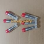
Information injection-pump assembly
ZEXEL
106661-5520
1066615520

Rating:
Service parts 106661-5520 INJECTION-PUMP ASSEMBLY:
1.
_
5.
AUTOM. ADVANCE MECHANIS
7.
COUPLING PLATE
8.
_
9.
_
11.
Nozzle and Holder
1660096508
12.
Open Pre:MPa(Kqf/cm2)
19.6(200)
15.
NOZZLE SET
Include in #1:
106661-5520
as INJECTION-PUMP ASSEMBLY
Cross reference number
Zexel num
Bosch num
Firm num
Name
106661-5520
INJECTION-PUMP ASSEMBLY
Information:
start by: a) remove pistons1. Check to be sure all coolant has been removed from the cylinder block.2. Put protection over the crankshaft bearing journals before removing cylinder liners.3. Put location marks on the cylinder liners with respect to their location in block. 4. Use tool setup (A) to remove the cylinder liners from block.5. Remove the seals from cylinder liners.6. Use a straight blade scraper to loosen the spacer plate (1) from cylinder block.
Use care when loosening the plate from cylinder block or damage to plate may result.
7. Remove the spacer plate (1).Install Cylinder Liners
1. Thoroughly clean both sides of spacer plate and top surface of block. Install spacer plate gasket and spacer plate on the cylinder block.
Make sure both sides of plate and top of block are clean and dry before installing gasket and plate. Do not put gasket adhesives or any other substance on these surfaces.
2. Put the cylinder liners in their respective positions in cylinder block. Install tool setup (B) and two cylinder head bolts and washers. Tighten the bolts to 70 5 lb.ft. (9.7 0.7 mkg).3. Check the cylinder liner projection using tool setup (C) as follows: a) Install the four spacers from tool group and four cylinder head bolts and washers. Tighten bolts to 70 5 lb.ft. (9.7 0.7 mkg).b) Use dial indicator, block, and gauge from the tool group to check liner projection at four locations around the liner.c) Cylinder liner projection must be .0030 to .0076 in. (0.076 to 0.193 mm). Projection between liners next to each other must not be different by more than .001 in. (0.025 mm). 4. Remove tool setup (B) and (C). Remove the liners from cylinder block.5. Install the O-ring seals on bottom of liners. Put liquid soap on the seals.
TYPICAL EXAMPLE6. Put oil on the filler band seal, and install the seal on top end of liner. Install the cylinder liners immediately into their respective locations in cylinder block using tool (A).
Do not let the filler band seal stay in oil except for a very short time because the oil will make the seal much bigger very fast. After putting oil on the filler band seal, install the liner immediately into block.
end by: a) install pistons.
Have questions with 106661-5520?
Group cross 106661-5520 ZEXEL
Nissan-Diesel
Nissan-Diesel
106661-5520
INJECTION-PUMP ASSEMBLY
