Information injection-pump assembly
BOSCH
F 019 Z10 625
f019z10625
ZEXEL
106661-5510
1066615510

Rating:
Service parts 106661-5510 INJECTION-PUMP ASSEMBLY:
1.
_
7.
COUPLING PLATE
8.
_
9.
_
11.
Nozzle and Holder
1660096502
12.
Open Pre:MPa(Kqf/cm2)
22.6(230)
15.
NOZZLE SET
Include in #1:
106661-5510
as INJECTION-PUMP ASSEMBLY
Cross reference number
BOSCH
F 019 Z10 625
f019z10625
ZEXEL
106661-5510
1066615510
Zexel num
Bosch num
Firm num
Name
Calibration Data:
Adjustment conditions
Test oil
1404 Test oil ISO4113 or {SAEJ967d}
1404 Test oil ISO4113 or {SAEJ967d}
Test oil temperature
degC
40
40
45
Nozzle and nozzle holder
105780-8140
Bosch type code
EF8511/9A
Nozzle
105780-0000
Bosch type code
DN12SD12T
Nozzle holder
105780-2080
Bosch type code
EF8511/9
Opening pressure
MPa
17.2
Opening pressure
kgf/cm2
175
Injection pipe
Outer diameter - inner diameter - length (mm) mm 8-3-600
Outer diameter - inner diameter - length (mm) mm 8-3-600
Overflow valve opening pressure
kPa
157
123
191
Overflow valve opening pressure
kgf/cm2
1.6
1.25
1.95
Tester oil delivery pressure
kPa
157
157
157
Tester oil delivery pressure
kgf/cm2
1.6
1.6
1.6
Direction of rotation (viewed from drive side)
Right R
Right R
Injection timing adjustment
Direction of rotation (viewed from drive side)
Right R
Right R
Injection order
1-4-2-6-
3-5
Pre-stroke
mm
3.2
3.15
3.25
Beginning of injection position
Drive side NO.1
Drive side NO.1
Difference between angles 1
Cal 1-4 deg. 60 59.5 60.5
Cal 1-4 deg. 60 59.5 60.5
Difference between angles 2
Cyl.1-2 deg. 120 119.5 120.5
Cyl.1-2 deg. 120 119.5 120.5
Difference between angles 3
Cal 1-6 deg. 180 179.5 180.5
Cal 1-6 deg. 180 179.5 180.5
Difference between angles 4
Cal 1-3 deg. 240 239.5 240.5
Cal 1-3 deg. 240 239.5 240.5
Difference between angles 5
Cal 1-5 deg. 300 299.5 300.5
Cal 1-5 deg. 300 299.5 300.5
Injection quantity adjustment
Adjusting point
A
Rack position
11.5
Pump speed
r/min
1150
1150
1150
Average injection quantity
mm3/st.
153.3
150.3
156.3
Max. variation between cylinders
%
0
-4
4
Fixing the lever
*
Boost pressure
kPa
60
60
Boost pressure
mmHg
450
450
Injection quantity adjustment_02
Adjusting point
B
Rack position
11.5
Pump speed
r/min
1000
1000
1000
Average injection quantity
mm3/st.
153.6
150.6
156.6
Max. variation between cylinders
%
0
-4
4
Fixing the lever
*
Boost pressure
kPa
60
60
Boost pressure
mmHg
450
450
Injection quantity adjustment_03
Adjusting point
C
Rack position
11.5
Pump speed
r/min
750
750
750
Average injection quantity
mm3/st.
149.6
147.6
151.6
Max. variation between cylinders
%
0
-4
4
Basic
*
Fixing the lever
*
Boost pressure
kPa
60
60
Boost pressure
mmHg
450
450
Injection quantity adjustment_04
Adjusting point
D
Rack position
11.5
Pump speed
r/min
400
400
400
Average injection quantity
mm3/st.
145.5
142.5
148.5
Max. variation between cylinders
%
0
-4
4
Fixing the lever
*
Boost pressure
kPa
60
60
Boost pressure
mmHg
450
450
Injection quantity adjustment_05
Adjusting point
E
Rack position
10.7
Pump speed
r/min
300
300
300
Average injection quantity
mm3/st.
118.6
115.6
121.6
Max. variation between cylinders
%
0
-4
4
Fixing the lever
*
Boost pressure
kPa
0
0
0
Boost pressure
mmHg
0
0
0
Injection quantity adjustment_06
Adjusting point
F
Rack position
6.1+-0.5
Pump speed
r/min
225
225
225
Average injection quantity
mm3/st.
11
10
12
Max. variation between cylinders
%
0
-10
10
Fixing the rack
*
Boost pressure
kPa
0
0
0
Boost pressure
mmHg
0
0
0
Boost compensator adjustment
Pump speed
r/min
300
300
300
Rack position
10.7
Boost pressure
kPa
33.3
33.3
33.3
Boost pressure
mmHg
250
250
250
Boost compensator adjustment_02
Pump speed
r/min
300
300
300
Rack position
11.1
Boost pressure
kPa
40
38.7
41.3
Boost pressure
mmHg
300
290
310
Boost compensator adjustment_03
Pump speed
r/min
300
300
300
Rack position
11.5
Boost pressure
kPa
46.7
46.7
46.7
Boost pressure
mmHg
350
350
350
Timer adjustment
Pump speed
r/min
700
Advance angle
deg.
0.3
Timer adjustment_02
Pump speed
r/min
750
Advance angle
deg.
0.5
Timer adjustment_03
Pump speed
r/min
850
Advance angle
deg.
0.5
0.1
0.9
Timer adjustment_04
Pump speed
r/min
1000
Advance angle
deg.
1.7
1.3
2.1
Timer adjustment_05
Pump speed
r/min
1150
Advance angle
deg.
3
2.6
3.4
Remarks
Finish
Finish
Test data Ex:
Governor adjustment

N:Pump speed
R:Rack position (mm)
(1)Lever ratio: RT
(2)Target shim dimension: TH
(3)Tolerance for racks not indicated: +-0.05mm.
(4)Rack limit using stop lever
(5)Damper spring setting
(6)Variable speed specification: idling adjustment
(7)Main spring setting
----------
RT=1 TH=2mm
----------
----------
RT=1 TH=2mm
----------
Speed control lever angle

F:Full speed
I:Idle
(1)Stopper bolt setting
----------
----------
a=11deg+4deg-3deg b=22deg+-4deg
----------
----------
a=11deg+4deg-3deg b=22deg+-4deg
0000000901

F:Full load
I:Idle
(1)Stopper bolt setting
----------
----------
a=32.5deg+-5deg b=42.5deg+-3deg
----------
----------
a=32.5deg+-5deg b=42.5deg+-3deg
Stop lever angle
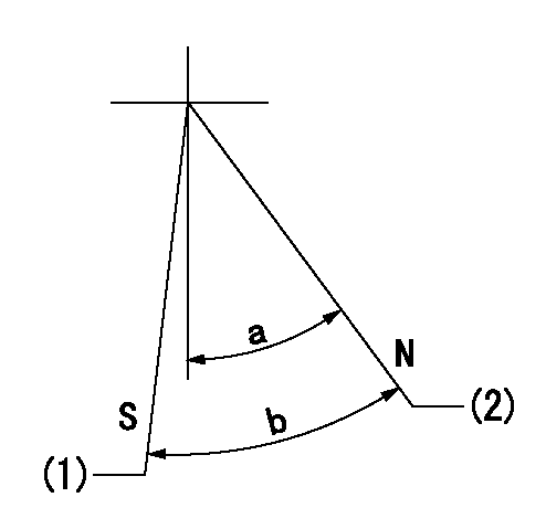
N:Pump normal
S:Stop the pump.
(1)Rack position = aa (non-injection rack position)
(2)Rack position bb
----------
aa=1.9-0.5mm bb=11.5mm
----------
a=27.5deg+-5deg b=28deg+-3deg
----------
aa=1.9-0.5mm bb=11.5mm
----------
a=27.5deg+-5deg b=28deg+-3deg
Timing setting

(1)Pump vertical direction
(2)Coupling's key groove position at No 1 cylinder's beginning of injection
(3)-
(4)-
----------
----------
a=(30deg)
----------
----------
a=(30deg)
Information:
2. Remove the four bolts (2) that hold flange to aftercooler cover. Loosen clamp (6) on the turbocharger, and turn housing until inlet pipe is away from camshaft housing.3. Remove the oil drain line for the turbocharger.4. Disconnect the wiring from the glow plugs.5. Remove the inner fuel injection lines (4).6. Disconnect the outer fuel injection lines from the camshaft housing.7. Disconnect the wiring (3) for the glow plugs from the camshaft housing.8. Remove lifting bracket (1) from housing. 9. Remove the two bolts (7), nuts (8), and locks.10. Remove the bolts (5) that hold the camshaft housing in position. 11. Fasten a hoist to the camshaft housing. Remove camshaft housing (9). Weight of housing is 100 lb. (45 kg).Install Camshaft Housing
1. Turn all adjustment screws counterclockwise as far as possible to get maximum valve lash. Turn the camshafts until the "V" timing marks on drive gears (2) and (3) are in alignment as shown. Install the timing pin in timing hole in camshaft housing.2. Check to be sure the No. 1 piston is at the "TOP CENTER COMPRESSION" position, and the timing bolt is installed in flywheel.
The procedure in Steps 1 and 2 must be followed or damage to the engine may result.
3. Fasten a hoist and put camshaft housing in position on engine with gear (3) engaged with gear (4) in cylinder head. Install the bolts (1), nuts, and locks that hold the camshaft housing in position. Install lifting bracket (5).4. Connect the fuel injection lines to outside of camshaft housing. Install inner lines. Tighten the nuts on lines to 30 5 lb.ft. (4.1 0.7 mkg).5. Remove the timing pin from camshaft housing and timing bolt from flywheel.6. Make the valve lash adjustment as follows: Make an adjustment to exhaust valves for cylinders 1-3-5 and inlet valves for cylinders 1-2-4. Turn the crankshaft 360° so No. 6 piston is at "TOP CENTER COMPRESSION" position. Make an adjustment to exhaust valves for cylinders 2-4-6 and inlet valves for cylinders 3-5-6.a) Turn screws clockwise until there is zero clearance between the button on screw and the valve.b) Turn screws counterclockwise four clicks to get .008 in. (0.2 mm) clearance for the inlet valves.c) Turn screws counterclockwise ten clicks to get .020 in. (0.5 mm) clearance for the exhaust valves.7. Connect the wiring for the glow plugs. Install the oil drain line for the turbocharger.8. Turn the housing to put pipe (6) into position, and install the four bolts. Tighten clamp (7).end by: a) install valve coverb) install alternatorDisassemble Camshaft Housing
start by: a) remove camshaft housing 1. Remove the four bolts (3) and lock from each drive gear. Remove the camshaft drive gears (1) and (2). 2. Remove the two bolts (5), lock, and plate (4) that hold camshafts in position. 3. Remove the inlet camshaft (6) and exhaust camshaft (7) from housing.4. Remove lifting bracket (8) from end of camshaft housing. 5. Remove the two bolts (11) that hold the rocker shafts in position.6. Remove the