Information injection-pump assembly
BOSCH
9 400 612 174
9400612174
ZEXEL
106661-5490
1066615490
NISSAN-DIESEL
1671396814
1671396814
Rating:
Service parts 106661-5490 INJECTION-PUMP ASSEMBLY:
1.
_
7.
COUPLING PLATE
8.
_
9.
_
11.
Nozzle and Holder
16600-96502
12.
Open Pre:MPa(Kqf/cm2)
22.6{230}
15.
NOZZLE SET
Include in #1:
106661-5490
as INJECTION-PUMP ASSEMBLY
Cross reference number
BOSCH
9 400 612 174
9400612174
ZEXEL
106661-5490
1066615490
NISSAN-DIESEL
1671396814
1671396814
Zexel num
Bosch num
Firm num
Name
106661-5490
9 400 612 174
1671396814 NISSAN-DIESEL
INJECTION-PUMP ASSEMBLY
PE6HT03 * K 14CA INJECTION PUMP ASSY PE6P,6PD PE
PE6HT03 * K 14CA INJECTION PUMP ASSY PE6P,6PD PE
Calibration Data:
Adjustment conditions
Test oil
1404 Test oil ISO4113 or {SAEJ967d}
1404 Test oil ISO4113 or {SAEJ967d}
Test oil temperature
degC
40
40
45
Nozzle and nozzle holder
105780-8140
Bosch type code
EF8511/9A
Nozzle
105780-0000
Bosch type code
DN12SD12T
Nozzle holder
105780-2080
Bosch type code
EF8511/9
Opening pressure
MPa
17.2
Opening pressure
kgf/cm2
175
Injection pipe
Outer diameter - inner diameter - length (mm) mm 8-3-600
Outer diameter - inner diameter - length (mm) mm 8-3-600
Overflow valve
132424-0620
Overflow valve opening pressure
kPa
157
123
191
Overflow valve opening pressure
kgf/cm2
1.6
1.25
1.95
Tester oil delivery pressure
kPa
157
157
157
Tester oil delivery pressure
kgf/cm2
1.6
1.6
1.6
Direction of rotation (viewed from drive side)
Right R
Right R
Injection timing adjustment
Direction of rotation (viewed from drive side)
Right R
Right R
Injection order
1-4-2-6-
3-5
Pre-stroke
mm
3.2
3.15
3.25
Beginning of injection position
Drive side NO.1
Drive side NO.1
Difference between angles 1
Cal 1-4 deg. 60 59.5 60.5
Cal 1-4 deg. 60 59.5 60.5
Difference between angles 2
Cyl.1-2 deg. 120 119.5 120.5
Cyl.1-2 deg. 120 119.5 120.5
Difference between angles 3
Cal 1-6 deg. 180 179.5 180.5
Cal 1-6 deg. 180 179.5 180.5
Difference between angles 4
Cal 1-3 deg. 240 239.5 240.5
Cal 1-3 deg. 240 239.5 240.5
Difference between angles 5
Cal 1-5 deg. 300 299.5 300.5
Cal 1-5 deg. 300 299.5 300.5
Injection quantity adjustment
Adjusting point
B
Rack position
10.8
Pump speed
r/min
750
750
750
Average injection quantity
mm3/st.
148.5
146.5
150.5
Max. variation between cylinders
%
0
-4
4
Basic
*
Fixing the lever
*
Injection quantity adjustment_02
Adjusting point
C
Rack position
3.6+-0.5
Pump speed
r/min
345
345
345
Average injection quantity
mm3/st.
12
11
13
Max. variation between cylinders
%
0
-10
10
Fixing the rack
*
Timer adjustment
Pump speed
r/min
975--
Advance angle
deg.
0
0
0
Remarks
Start
Start
Timer adjustment_02
Pump speed
r/min
925
Advance angle
deg.
0.5
Timer adjustment_03
Pump speed
r/min
1100
Advance angle
deg.
0.75
0.25
1.25
Timer adjustment_04
Pump speed
r/min
-
Advance angle
deg.
1.2
1.2
1.2
Remarks
Measure the actual speed, stop
Measure the actual speed, stop
Test data Ex:
Governor adjustment
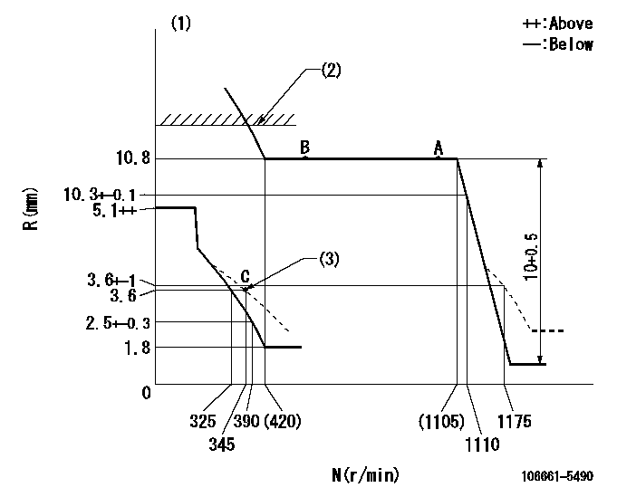
N:Pump speed
R:Rack position (mm)
(1)Tolerance for racks not indicated: +-0.05mm.
(2)Rack limit using the stop lever: R1
(3)Damper spring setting
----------
R1=11.5+-0.1mm
----------
----------
R1=11.5+-0.1mm
----------
Speed control lever angle

F:Full speed
----------
----------
a=6deg+-5deg
----------
----------
a=6deg+-5deg
0000000901
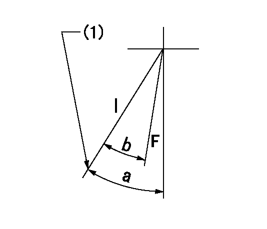
F:Full load
I:Idle
(1)Stopper bolt setting
----------
----------
a=33deg+-5deg b=33deg+-3deg
----------
----------
a=33deg+-5deg b=33deg+-3deg
Stop lever angle
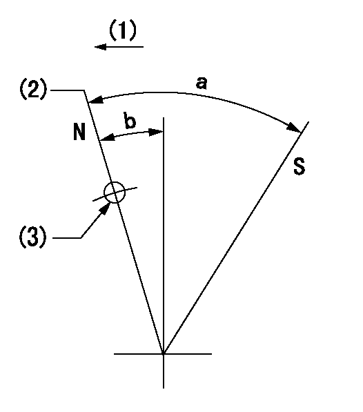
N:Pump normal
S:Stop the pump.
(1)Drive side
(2)Rack position = aa
(3)Use the hole at R = bb
----------
aa=11.5+-0.1mm bb=32mm
----------
a=29.5deg+-5deg b=4deg+-5deg
----------
aa=11.5+-0.1mm bb=32mm
----------
a=29.5deg+-5deg b=4deg+-5deg
0000001501 GOV FULL LOAD ADJUSTMENT
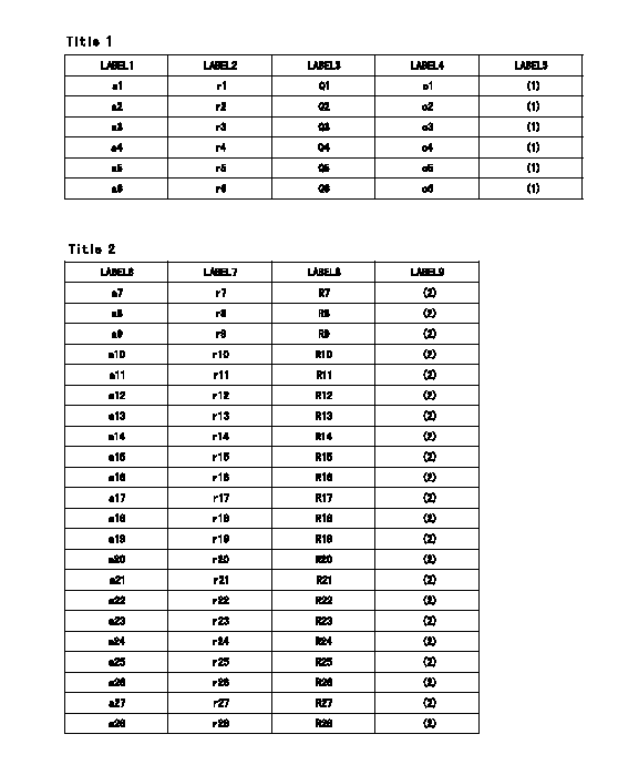
Title1:Full load stopper adjustment
Title2:Governor set speed
LABEL1:Distinguishing
LABEL2:Pump speed (r/min)
LABEL3:Ave. injection quantity (mm3/st)
LABEL4:Max. var. bet. cyl.
LABEL5:Remarks
LABEL6:Distinguishing
LABEL7:Governor set speed (r/min)
LABEL8:Maximum no-load speed (r/min)
LABEL9:Remarks
(1)Adjustment conditions are the same as those for measuring injection quantity.
(2)At high idle rack position L
----------
L=4mm
----------
a1=E a2=B a3=C a4=- a5=- a6=- r1=750r/min r2=750r/min r3=750r/min r4=- r5=- r6=- Q1=165.5+-2mm3/st Q2=148.5+-2mm3/st Q3=142+-2mm3/st Q4=- Q5=- Q6=- c1=+-4% c2=+-4% c3=+-4% c4=- c5=- c6=- a7=E-22 a8=E-21 a9=E-20 a10=E-19 a11=E-18 a12=B-22 a13=B-21 a14=B-20 a15=B-19 a16=B-18 a17=C-22 a18=C-21 a19=C-20 a20=C-19 a21=C-18 a22=C-17 a23=- a24=- a25=- a26=- a27=- a28=- r7=1100r/min r8=1050r/min r9=1000r/min r10=950r/min r11=900r/min r12=1100r/min r13=1050r/min r14=1000r/min r15=950r/min r16=900r/min r17=1100r/min r18=1050r/min r19=1000r/min r20=950r/min r21=900r/min r22=850r/min r23=- r24=- r25=- r26=- r27=- r28=- R7=1180+-27r/min R8=1130+-26r/min R9=1075+-25r/min R10=1020+-23r/min R11=965+-22r/min R12=1180+-27r/min R13=1130+-26r/min R14=1075+-25r/min R15=1020+-23r/min R16=965+-22r/min R17=1180+-27r/min R18=1130+-26r/min R19=1075+-25r/min R20=1020+-23r/min R21=965+-22r/min R22=915+-22r/min R23=- R24=- R25=- R26=- R27=- R28=-
----------
L=4mm
----------
a1=E a2=B a3=C a4=- a5=- a6=- r1=750r/min r2=750r/min r3=750r/min r4=- r5=- r6=- Q1=165.5+-2mm3/st Q2=148.5+-2mm3/st Q3=142+-2mm3/st Q4=- Q5=- Q6=- c1=+-4% c2=+-4% c3=+-4% c4=- c5=- c6=- a7=E-22 a8=E-21 a9=E-20 a10=E-19 a11=E-18 a12=B-22 a13=B-21 a14=B-20 a15=B-19 a16=B-18 a17=C-22 a18=C-21 a19=C-20 a20=C-19 a21=C-18 a22=C-17 a23=- a24=- a25=- a26=- a27=- a28=- r7=1100r/min r8=1050r/min r9=1000r/min r10=950r/min r11=900r/min r12=1100r/min r13=1050r/min r14=1000r/min r15=950r/min r16=900r/min r17=1100r/min r18=1050r/min r19=1000r/min r20=950r/min r21=900r/min r22=850r/min r23=- r24=- r25=- r26=- r27=- r28=- R7=1180+-27r/min R8=1130+-26r/min R9=1075+-25r/min R10=1020+-23r/min R11=965+-22r/min R12=1180+-27r/min R13=1130+-26r/min R14=1075+-25r/min R15=1020+-23r/min R16=965+-22r/min R17=1180+-27r/min R18=1130+-26r/min R19=1075+-25r/min R20=1020+-23r/min R21=965+-22r/min R22=915+-22r/min R23=- R24=- R25=- R26=- R27=- R28=-
Timing setting

(1)Pump vertical direction
(2)Coupling's key groove position at No 1 cylinder's beginning of injection
(3)-
(4)-
----------
----------
a=(30deg)
----------
----------
a=(30deg)
Information:
start by: a) separation of governor from fuel injection pump housing1. Remove the cover (16) from rack centering pin. Move the rack to the fuel "OFF" position, and push in on the centering pin (15). Install the cover (16) as shown to keep the centering pin in position during disassembly and assembly of injection pump housing. 2. Move the rack toward the fuel "ON" position until the slot in rack (13) is against the rack centering pin (15). The rack is now in the "CENTER" position.
Do not try to remove the fuel injection pumps if the rack is not in "CENTER" position.
3. Remove the fuel injection pumps as follows: a) Remove the caps and felt washer (1).b) Install wrench (A), and remove the bushing (2) from housing. c) Install extractor (B).d) Remove the bushing (2) and wrench (A).e) Remove the seal (3).f) Lift the fuel injection pump up and out of housing.g) Remove the spacer (9). Keep the spacer (9) together with its respective fuel injection pump. Put identification on the pumps and spacers as to their location in the pump housing.4. Disassemble the fuel injection pumps as follows: a) Remove the ring (7), bonnet (4), check valve (6), and spring (5) from barrel (8).b) Remove the plunger assembly (11), washer (12), and spring (10) from barrel (8).
Be very careful when disassembling and assembling the fuel injection pumps to prevent damage to the plunger surfaces. The barrel and plunger assemblies are fitted together, and must not be used with other barrels or plunger assemblies.
5. Remove the rack centering pin, spring, and cover. 6. Remove the rack (13), and lifters (14). Put identification on the lifters as to their location in the pump housing. Keep the lifters with their respective pumps and spacers. 7. Remove the bolt, lock, and plate (17) from the camshaft. Remove the spring and gear assembly (18).8. Remove the camshaft (20) from pump housing.9. Remove the rack bearings (19) from housing. 10. Use tool setup (C) to remove the camshaft bearings from the fuel injection pump housing.Assemble Fuel Injection Pump Housing
1. Use tool group (D) to install the rack bearing in the accessory drive housing end of injection pump housing.2. Install the rack bearing in governor end of housing using tool setup (E). The bearing must be installed .195 .005 in. (4.95 0.13 mm) below outside face of pump housing.3. Use tool group (C) to install the camshaft bearings in housing. Make sure the oil holes in bearings are in alignment with oil holes in pump housing. 4. Put clean engine oil on the camshaft bearings. Install the camshaft (1) in pump housing. 5. Install the gear (3), spring, plate, lock, and bolt (2) on the camshaft.6. Put clean engine oil on lobes of camshaft. 7. Install the lifters (4) in their respective positions in pump housing. Install the spacers in their correct locations in housing. If new lifters are to be installed, it will be necessary to check the timing
Have questions with 106661-5490?
Group cross 106661-5490 ZEXEL
Nissan-Diesel
Nissan-Diesel
Nissan-Diesel
Nissan-Diesel
Nissan-Diesel
Nissan-Diesel
106661-5490
9 400 612 174
1671396814
INJECTION-PUMP ASSEMBLY
PE6HT03
PE6HT03