Information injection-pump assembly
ZEXEL
106661-5470
1066615470

Rating:
Service parts 106661-5470 INJECTION-PUMP ASSEMBLY:
1.
_
7.
COUPLING PLATE
8.
_
9.
_
11.
Nozzle and Holder
16600-96502
12.
Open Pre:MPa(Kqf/cm2)
22.6{230}
15.
NOZZLE SET
Include in #1:
106661-5470
as INJECTION-PUMP ASSEMBLY
Cross reference number
ZEXEL
106661-5470
1066615470
Zexel num
Bosch num
Firm num
Name
106661-5470
INJECTION-PUMP ASSEMBLY
Calibration Data:
Adjustment conditions
Test oil
1404 Test oil ISO4113 or {SAEJ967d}
1404 Test oil ISO4113 or {SAEJ967d}
Test oil temperature
degC
40
40
45
Nozzle and nozzle holder
105780-8140
Bosch type code
EF8511/9A
Nozzle
105780-0000
Bosch type code
DN12SD12T
Nozzle holder
105780-2080
Bosch type code
EF8511/9
Opening pressure
MPa
17.2
Opening pressure
kgf/cm2
175
Injection pipe
Outer diameter - inner diameter - length (mm) mm 8-3-600
Outer diameter - inner diameter - length (mm) mm 8-3-600
Overflow valve opening pressure
kPa
157
123
191
Overflow valve opening pressure
kgf/cm2
1.6
1.25
1.95
Tester oil delivery pressure
kPa
157
157
157
Tester oil delivery pressure
kgf/cm2
1.6
1.6
1.6
Direction of rotation (viewed from drive side)
Right R
Right R
Injection timing adjustment
Direction of rotation (viewed from drive side)
Right R
Right R
Injection order
1-4-2-6-
3-5
Pre-stroke
mm
3.2
3.15
3.25
Beginning of injection position
Drive side NO.1
Drive side NO.1
Difference between angles 1
Cal 1-4 deg. 60 59.5 60.5
Cal 1-4 deg. 60 59.5 60.5
Difference between angles 2
Cyl.1-2 deg. 120 119.5 120.5
Cyl.1-2 deg. 120 119.5 120.5
Difference between angles 3
Cal 1-6 deg. 180 179.5 180.5
Cal 1-6 deg. 180 179.5 180.5
Difference between angles 4
Cal 1-3 deg. 240 239.5 240.5
Cal 1-3 deg. 240 239.5 240.5
Difference between angles 5
Cal 1-5 deg. 300 299.5 300.5
Cal 1-5 deg. 300 299.5 300.5
Injection quantity adjustment
Adjusting point
A
Rack position
10.9
Pump speed
r/min
750
750
750
Average injection quantity
mm3/st.
149.6
147.6
151.6
Max. variation between cylinders
%
0
-4
4
Basic
*
Fixing the lever
*
Boost pressure
kPa
26.7
26.7
Boost pressure
mmHg
200
200
Injection quantity adjustment_02
Adjusting point
B
Rack position
10.9
Pump speed
r/min
1150
1150
1150
Average injection quantity
mm3/st.
153.3
150.3
156.3
Max. variation between cylinders
%
0
-4
4
Fixing the lever
*
Boost pressure
kPa
26.7
26.7
Boost pressure
mmHg
200
200
Injection quantity adjustment_03
Adjusting point
C
Rack position
5.7+-0.5
Pump speed
r/min
225
225
225
Average injection quantity
mm3/st.
11
10
12
Max. variation between cylinders
%
0
-10
10
Fixing the rack
*
Boost pressure
kPa
0
0
0
Boost pressure
mmHg
0
0
0
Boost compensator adjustment
Pump speed
r/min
300
300
300
Rack position
10.1
Boost pressure
kPa
6.7
4
6.7
Boost pressure
mmHg
50
30
50
Boost compensator adjustment_02
Pump speed
r/min
300
300
300
Rack position
10.6
Boost pressure
kPa
10.7
9.4
12
Boost pressure
mmHg
80
70
90
Boost compensator adjustment_03
Pump speed
r/min
300
300
300
Rack position
10.9
Boost pressure
kPa
13.3
13.3
13.3
Boost pressure
mmHg
100
100
100
Timer adjustment
Pump speed
r/min
700
Advance angle
deg.
0.3
Timer adjustment_02
Pump speed
r/min
750
Advance angle
deg.
0.5
Timer adjustment_03
Pump speed
r/min
850
Advance angle
deg.
0.5
0.1
0.9
Timer adjustment_04
Pump speed
r/min
1000
Advance angle
deg.
1.7
1.3
2.1
Timer adjustment_05
Pump speed
r/min
1150
Advance angle
deg.
3
2.6
3.4
Remarks
Finish
Finish
Test data Ex:
Governor adjustment

N:Pump speed
R:Rack position (mm)
(1)Boost compensator stroke: BCL
(2)Rack limit using stop lever
(3)Damper spring setting: DL
----------
BCL=0.8+-0.1mm DL=4.7-0.2mm
----------
----------
BCL=0.8+-0.1mm DL=4.7-0.2mm
----------
0000000901

F:Full load
I:Idle
(1)Stopper bolt setting
----------
----------
a=12deg+-5deg b=21deg+-3deg
----------
----------
a=12deg+-5deg b=21deg+-3deg
Stop lever angle
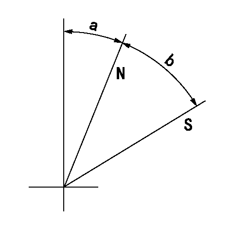
N:Pump normal
S:Stop the pump.
----------
----------
a=3deg+-5deg b=32deg+-3deg
----------
----------
a=3deg+-5deg b=32deg+-3deg
0000001501 ACS
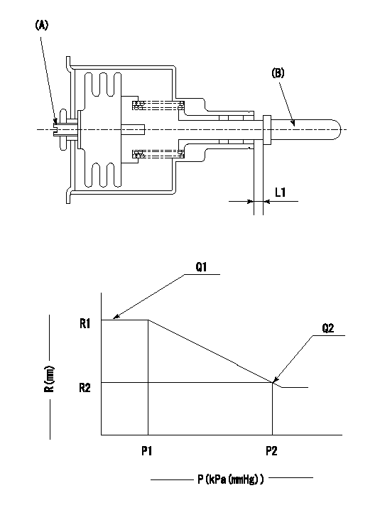
(A) Set screw
(B) Push rod 1
1. Aneroid compensator unit adjustment
(1)Screw in (A) to obtain L1.
2. Adjustment following governor installation
(1)Set the speed of the pump to N1 r/min and fix the control lever at the full set position.
(2)Screw in the aneroid compensator to obtain the performance shown in the graph above.
----------
N1=1150r/min L1=(0.6~0.9)mm
----------
R1=10.9mm R2=(10.1)mm P1=80kPa(600mmHg) P2=58+-0.7kPa(435+-5mmHg) Q1=153.3+-3cm3/1000st Q2=134.2+-3cm3/1000st
----------
N1=1150r/min L1=(0.6~0.9)mm
----------
R1=10.9mm R2=(10.1)mm P1=80kPa(600mmHg) P2=58+-0.7kPa(435+-5mmHg) Q1=153.3+-3cm3/1000st Q2=134.2+-3cm3/1000st
Timing setting

(1)Pump vertical direction
(2)Coupling's key groove position at No 1 cylinder's beginning of injection
(3)-
(4)-
----------
----------
a=(30deg)
----------
----------
a=(30deg)
Information:
2. Remove the two bolts (1) from transfer pump, and pull the pump out of accessory drive housing.3. Remove the four bolts and lock from retainer (3). Remove the retainer.4. Remove the drive gear (2). 5. Remove the two bolts, locks, and plate (5).6. Remove the variable timing unit (4) from the accessory drive housing.Install Variable Timing Unit
1. Put the variable timing unit (1) in position in the accessory drive housing.2. Install the retaining plate, locks, and two bolts.3. Install the drive gear, retainer, lock, and four bolts. Do not tighten the four bolts.4. Make an adjustment to the timing of the camshaft for the fuel injection pump. See FUEL INJECTION PUMP CAMSHAFT TIMING in TESTING AND ADJUSTING. 5. Install the cover (4) on timing gear housing.6. Put the transfer pump (3) in position on the accessory drive housing, and install the two bolts (2).7. Check to be sure all timing pins and bolts have been removed from their timing holes, and are installed in their storage positions.Disassemble Variable Timing Unit
start by: a) remove variable timing unit 1. Push down on retainer (1), and remove the pin (2).2. Remove the retainer and spring. 3. Use a hammer and punch to remove the dowels (4). Remove the two weights.4. Remove the piston and rod assembly (5) from shaft assembly (3).5. Remove the pins from nut and rod.6. Remove the rod, nut, spring, and valve from the piston assembly.Assemble Variable Timing Unit
1. Install the valve, spring, and nut on the piston assembly. Turn the nut until the distance (X) between bottom face of nut and the piston is 1.760 in. (44.7 mm). Drill a .095 .002 in. (2.41 0.05 mm) diameter hole through the nut and the threads of piston assembly. Install the pin in nut. 1. Install the rod tight against the nut. Take a measurement .156 in. (3.96 mm) from top face of nut, and put a mark at this location on rod. Drill a .095 .0.05 mm) diameter hole (1) through the rod and piston assembly at this location. Install the pin in rod.3. Install the piston and rod assembly in the shaft assembly. Install the spring, retainer, and pin in shaft assembly.4. Install the weights and dowels. Use a hammer and punch to fasten both ends of the dowels in place. Both weights must move freely after the dowels have been fastened in place.end by: a) install variable timing unit
Have questions with 106661-5470?
Group cross 106661-5470 ZEXEL
Nissan-Diesel
Nissan-Diesel
Nissan-Diesel
Nissan-Diesel
Nissan-Diesel
106661-5470
INJECTION-PUMP ASSEMBLY