Information injection-pump assembly
BOSCH
9 400 616 623
9400616623
ZEXEL
106661-5433
1066615433
NISSAN-DIESEL
1671396805
1671396805

Rating:
Service parts 106661-5433 INJECTION-PUMP ASSEMBLY:
1.
_
7.
COUPLING PLATE
8.
_
9.
_
11.
Nozzle and Holder
1660096508
12.
Open Pre:MPa(Kqf/cm2)
19.6(200)

15.
NOZZLE SET
Include in #1:
106661-5433
as INJECTION-PUMP ASSEMBLY
Cross reference number
BOSCH
9 400 616 623
9400616623
ZEXEL
106661-5433
1066615433
NISSAN-DIESEL
1671396805
1671396805
Zexel num
Bosch num
Firm num
Name
106661-5433
9 400 616 623
1671396805 NISSAN-DIESEL
INJECTION-PUMP ASSEMBLY
PE6H * K
PE6H * K
Calibration Data:
Adjustment conditions
Test oil
1404 Test oil ISO4113 or {SAEJ967d}
1404 Test oil ISO4113 or {SAEJ967d}
Test oil temperature
degC
40
40
45
Nozzle and nozzle holder
105780-8140
Bosch type code
EF8511/9A
Nozzle
105780-0000
Bosch type code
DN12SD12T
Nozzle holder
105780-2080
Bosch type code
EF8511/9
Opening pressure
MPa
17.2
Opening pressure
kgf/cm2
175
Injection pipe
Outer diameter - inner diameter - length (mm) mm 8-3-600
Outer diameter - inner diameter - length (mm) mm 8-3-600
Overflow valve opening pressure
kPa
157
123
191
Overflow valve opening pressure
kgf/cm2
1.6
1.25
1.95
Tester oil delivery pressure
kPa
157
157
157
Tester oil delivery pressure
kgf/cm2
1.6
1.6
1.6
Direction of rotation (viewed from drive side)
Right R
Right R
Injection timing adjustment
Direction of rotation (viewed from drive side)
Right R
Right R
Injection order
1-4-2-6-
3-5
Pre-stroke
mm
3.65
3.6
3.7
Beginning of injection position
Drive side NO.1
Drive side NO.1
Difference between angles 1
Cal 1-4 deg. 60 59.5 60.5
Cal 1-4 deg. 60 59.5 60.5
Difference between angles 2
Cyl.1-2 deg. 120 119.5 120.5
Cyl.1-2 deg. 120 119.5 120.5
Difference between angles 3
Cal 1-6 deg. 180 179.5 180.5
Cal 1-6 deg. 180 179.5 180.5
Difference between angles 4
Cal 1-3 deg. 240 239.5 240.5
Cal 1-3 deg. 240 239.5 240.5
Difference between angles 5
Cal 1-5 deg. 300 299.5 300.5
Cal 1-5 deg. 300 299.5 300.5
Injection quantity adjustment
Adjusting point
A
Rack position
12
Pump speed
r/min
650
650
650
Average injection quantity
mm3/st.
119.2
117.2
121.2
Max. variation between cylinders
%
0
-4
4
Basic
*
Fixing the lever
*
Injection quantity adjustment_02
Adjusting point
B
Rack position
11.8
Pump speed
r/min
500
500
500
Average injection quantity
mm3/st.
105.7
102.7
108.7
Max. variation between cylinders
%
0
-4
4
Fixing the lever
*
Injection quantity adjustment_03
Adjusting point
C
Rack position
8+-0.5
Pump speed
r/min
240
240
240
Average injection quantity
mm3/st.
10.5
9.2
11.8
Max. variation between cylinders
%
0
-10
10
Fixing the rack
*
Injection quantity adjustment_04
Adjusting point
D
Rack position
14+-0.1
Pump speed
r/min
40
40
40
Average injection quantity
mm3/st.
106
106
Fixing the lever
*
Rack limit
*
Timer adjustment
Pump speed
r/min
200+100
Advance angle
deg.
1.6
1.1
2.1
Remarks
Start
Start
Timer adjustment_02
Pump speed
r/min
500-150
Advance angle
deg.
0
0
0
Timer adjustment_03
Pump speed
r/min
925+-30
Advance angle
deg.
0
0
0
Timer adjustment_04
Pump speed
r/min
1100
Advance angle
deg.
5
4.5
5.5
Remarks
Finish
Finish
Test data Ex:
Governor adjustment
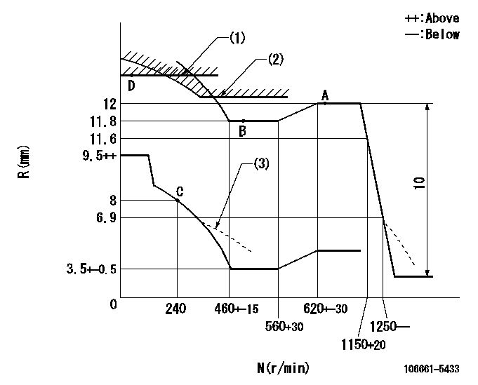
N:Pump speed
R:Rack position (mm)
(1)Rack limit using the stop lever: R1
(2)Excess fuel setting for starting: SXL
(3)Damper spring setting: DL
----------
R1=14+-0.1mm SXL=12+0.2mm DL=6.9-0.2mm
----------
----------
R1=14+-0.1mm SXL=12+0.2mm DL=6.9-0.2mm
----------
Speed control lever angle

F:Full speed
----------
----------
a=22.5deg+-5deg
----------
----------
a=22.5deg+-5deg
0000000901

F:Full load
I:Idle
(1)Stopper bolt setting
----------
----------
a=15deg+-5deg b=31deg+-3deg
----------
----------
a=15deg+-5deg b=31deg+-3deg
Stop lever angle
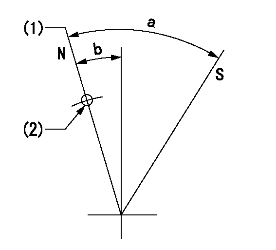
N:Pump normal
S:Stop the pump.
(1)Rack position = aa
(2)Use the hole at R = bb
----------
aa=14+-0.1mm bb=32mm
----------
a=36.5deg+-5deg b=11deg+-5deg
----------
aa=14+-0.1mm bb=32mm
----------
a=36.5deg+-5deg b=11deg+-5deg
Timing setting

(1)Pump vertical direction
(2)Coupling's key groove position at No 1 cylinder's beginning of injection
(3)-
(4)-
----------
----------
a=(30deg)
----------
----------
a=(30deg)
Information:
ACTION REQUIRED
Refer to the Service Manual if/as necessary.
Inspect the engine for 20R-1282 Fuel Injectors with serial numbers LESS THAN 1240557.
If the engine has 20R-1282 Fuel Injectors with serial numbers LESS THAN 1240557, replace only the 20R-1282 Fuel Injectors with serial numbers LESS THAN 1240557 with 392-0222 Fuel Injectors.
Refer to Image 1 for the part number and serial number locations.
Record the serial number(s) and part number for the injector(s) removed.
Image1
SERVICE CLAIM ALLOWANCES
Product smu/age whichever comes first Caterpillar Dealer Suggested Customer Suggested
Parts % Labor Hrs% Parts % Labor Hrs% Parts % Labor Hrs%
*******Group 1*******
0-4380 hrs,
0-6 mo 100.0% 100.0% 0.0% 0.0% 0.0% 0.0%
This is a 1.0-hour job for Group 1
If there has been a previous repair, part age/hours will apply. Retain a copy of the previous repair invoice in the dealer's records for audit purposes, and specify repair date and machine hours in the "Additional Comments" section of the warranty claim.
The serial number(s) and part number for the injector(s) removed must be included in the claim story.
1.0 hour will be allowed for inspecting for suspect injectors.
1.0 hour will be allowed for replacing each 20R-1282 Fuel Injector in the engine with a 392-0222 Fuel Injector.
Reasonable travel time and mileage will be allowed.
Product smu/age whichever comes first Caterpillar Dealer Suggested Customer Suggested
Parts % Labor Hrs% Parts % Labor Hrs% Parts % Labor Hrs%
*******Group 2*******
0-4380 hrs,
0-6 mo 100.0% 100.0% 0.0% 0.0% 0.0% 0.0%
This is a 2.0-hour job for Group 2
If there has been a previous repair, part age/hours will apply. Retain a copy of the previous repair invoice in the dealer's records for audit purposes, and specify repair date and machine hours in the "Additional Comments" section of the warranty claim.
The serial number(s) and part number for the injector(s) removed must be included in the claim story.
2.0 hours will be allowed for inspecting for suspect injectors.
1.0 hour will be allowed for replacing each 20R-1282 Fuel Injector in the engine with a 392-0222 Fuel Injector.
Reasonable travel time and mileage will be allowed.
PARTS DISPOSITION
Handle the parts in accordance with your Warranty Bulletin on warranty parts handling.
Have questions with 106661-5433?
Group cross 106661-5433 ZEXEL
Nissan-Diesel
Nissan-Diesel
Nissan-Diesel
106661-5433
9 400 616 623
1671396805
INJECTION-PUMP ASSEMBLY
PE6H
PE6H