Information injection-pump assembly
BOSCH
9 400 616 622
9400616622
ZEXEL
106661-5422
1066615422
NISSAN-DIESEL
1671396806
1671396806

Rating:
Service parts 106661-5422 INJECTION-PUMP ASSEMBLY:
1.
_
7.
COUPLING PLATE
8.
_
9.
_
11.
Nozzle and Holder
1660096508
12.
Open Pre:MPa(Kqf/cm2)
19.6(200)

15.
NOZZLE SET
Include in #1:
106661-5422
as INJECTION-PUMP ASSEMBLY
Cross reference number
BOSCH
9 400 616 622
9400616622
ZEXEL
106661-5422
1066615422
NISSAN-DIESEL
1671396806
1671396806
Zexel num
Bosch num
Firm num
Name
106661-5422
9 400 616 622
1671396806 NISSAN-DIESEL
INJECTION-PUMP ASSEMBLY
PE6 * K
PE6 * K
Calibration Data:
Adjustment conditions
Test oil
1404 Test oil ISO4113 or {SAEJ967d}
1404 Test oil ISO4113 or {SAEJ967d}
Test oil temperature
degC
40
40
45
Nozzle and nozzle holder
105780-8140
Bosch type code
EF8511/9A
Nozzle
105780-0000
Bosch type code
DN12SD12T
Nozzle holder
105780-2080
Bosch type code
EF8511/9
Opening pressure
MPa
17.2
Opening pressure
kgf/cm2
175
Injection pipe
Outer diameter - inner diameter - length (mm) mm 8-3-600
Outer diameter - inner diameter - length (mm) mm 8-3-600
Overflow valve opening pressure
kPa
157
123
191
Overflow valve opening pressure
kgf/cm2
1.6
1.25
1.95
Tester oil delivery pressure
kPa
157
157
157
Tester oil delivery pressure
kgf/cm2
1.6
1.6
1.6
Direction of rotation (viewed from drive side)
Right R
Right R
Injection timing adjustment
Direction of rotation (viewed from drive side)
Right R
Right R
Injection order
1-4-2-6-
3-5
Pre-stroke
mm
3.65
3.6
3.7
Beginning of injection position
Drive side NO.1
Drive side NO.1
Difference between angles 1
Cal 1-4 deg. 60 59.5 60.5
Cal 1-4 deg. 60 59.5 60.5
Difference between angles 2
Cyl.1-2 deg. 120 119.5 120.5
Cyl.1-2 deg. 120 119.5 120.5
Difference between angles 3
Cal 1-6 deg. 180 179.5 180.5
Cal 1-6 deg. 180 179.5 180.5
Difference between angles 4
Cal 1-3 deg. 240 239.5 240.5
Cal 1-3 deg. 240 239.5 240.5
Difference between angles 5
Cal 1-5 deg. 300 299.5 300.5
Cal 1-5 deg. 300 299.5 300.5
Injection quantity adjustment
Adjusting point
A
Rack position
12.2
Pump speed
r/min
750
750
750
Average injection quantity
mm3/st.
122.3
120.3
124.3
Max. variation between cylinders
%
0
-4
4
Basic
*
Fixing the lever
*
Injection quantity adjustment_02
Adjusting point
-
Rack position
7+-0.5
Pump speed
r/min
240
240
240
Average injection quantity
mm3/st.
10
8.7
11.3
Max. variation between cylinders
%
0
-10
10
Fixing the rack
*
Remarks
Adjust only variation between cylinders; adjust governor according to governor specifications.
Adjust only variation between cylinders; adjust governor according to governor specifications.
Timer adjustment
Pump speed
r/min
950--
Advance angle
deg.
0
0
0
Remarks
Start
Start
Timer adjustment_02
Pump speed
r/min
900
Advance angle
deg.
0.5
Timer adjustment_03
Pump speed
r/min
1150
Advance angle
deg.
5
4.5
5.5
Remarks
Finish
Finish
Test data Ex:
Governor adjustment
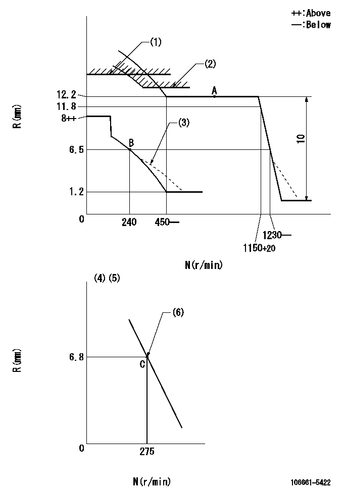
N:Pump speed
R:Rack position (mm)
(1)Rack limit using the stop lever: R1
(2)Excess fuel setting for starting: SXL
(3)Damper spring setting: DL
(4)Variable speed specification: idling adjustment
(5)Fix the lever at the full-load position at delivery.
(6)Main spring setting
----------
R1=14+-0.1mm SXL=12.2+0.2mm DL=5.5-0.5mm
----------
----------
R1=14+-0.1mm SXL=12.2+0.2mm DL=5.5-0.5mm
----------
Speed control lever angle
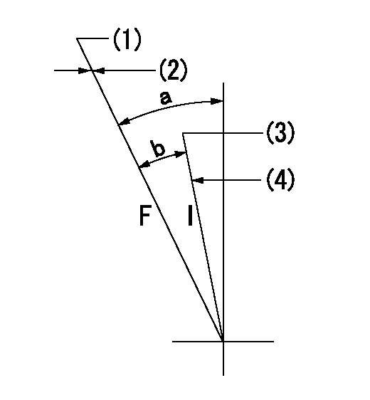
F:Full speed
I:Idle
(1)Set the pump speed at aa
(2)Set the stopper bolt (fixed at full-load position at delivery.)
(3)Set the pump speed at bb.
(4)Stopper bolt setting
----------
aa=1150r/min bb=275r/min
----------
a=31deg+-5deg b=23deg+-5deg
----------
aa=1150r/min bb=275r/min
----------
a=31deg+-5deg b=23deg+-5deg
0000000901

F:Full load
I:Idle
(1)Stopper bolt setting
----------
----------
a=15deg+-5deg b=40.5deg+-3deg
----------
----------
a=15deg+-5deg b=40.5deg+-3deg
Stop lever angle
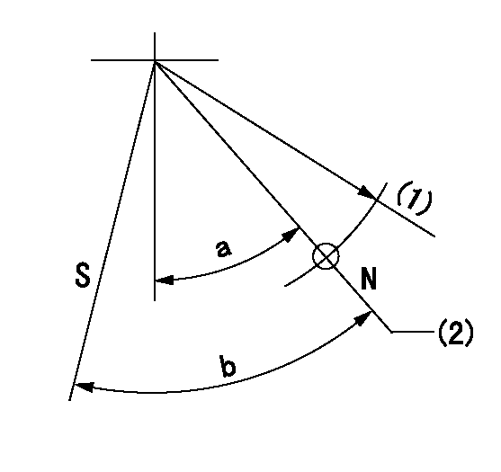
N:Pump normal
S:Stop the pump.
(1)R = aa
(2)Rack position bb
----------
aa=50mm bb=14+-0.1mm
----------
a=34.5deg+-5deg b=36.5deg+-3deg
----------
aa=50mm bb=14+-0.1mm
----------
a=34.5deg+-5deg b=36.5deg+-3deg
Timing setting

(1)Pump vertical direction
(2)Coupling's key groove position at No 1 cylinder's beginning of injection
(3)-
(4)-
----------
----------
a=(30deg)
----------
----------
a=(30deg)
Information:
CompactorCB68B (S/N: 496100-100)Asphalt PaverAP1055F (S/N: RLM1-105)AP555F (S/N: 5F51-101)AP600F (S/N: LR61-108)AP655F (S/N: 4801-103; P651-124; ML61-113; 4791-122,125-125)Excavator320D2 (S/N: BW21-235; CY21-192; ZBH1-975,10001-10185)323D2 (S/N: FLC1-219,10001-10004; KCE1-428; JEG1-257; PJP1-1331; YCR1-288; TDT1-560,10001-10135; KBX1-191,10001-10006)326D2 (S/N: REC1-197,199-199,202-203,205-206,208-212; MZH1-282,10001-10006; JFL1-174; XAM1-510,10001-10060; MGW1-313; NBX1-156; KGY1-323)329D2 (S/N: RGA1-309; KJB1-180; SHJ1-190; TMJ1-376; WDT145-145; THW1-506,509-554)330D2 (S/N: PTE1-211; ZBF1-514,10001-10073,10076-10088; RCK1-357; SZK1-561,10001-10143)Generator SetXQP150 (S/N: PJ71-105,107-107,109-112)Motor Grader120L (S/N: E93100-100)120N (S/N: E94100-100; E951-101)Soil Compactor815K (S/N: WCS100-100,201-201)TelehandlerTL1055D (S/N: MNT63-63,150-181,183-186,188-188,192-192)TL1255D (S/N: MYW1-157,160-161,15700-15700)Track-Type TractorD3K2 (S/N: FT31-103,2100-2115,2119-2119; LT31-113,2110-2111)D4K2 (S/N: RT3130-130,2130-2130)D5K2 (S/N: WT31-157,2140-2174; YT31-157,2150-2163,2167-2167)D5R2 (S/N: R5A150-150,152-158,161-162)D6K2 (S/N: MXK1-273; RPR1-307)D6N (S/N: P5T1-166)Vibratory Soil CompactorCS79B (S/N: CM71-101)Wheel Loader924K (S/N: KW41-395; ENC1-1566; HJF1-101,250-818; SNZ100-100,250-430)930K (S/N: DYB1-486; EYE1-127,250-789; FRK1-131,350-433; P3K1-195; TNY1-69)938K (S/N: W8K1-306; REP150-150,450-625; XXT1-137,350-962; HFW1-932)950 GC (S/N: M5K1-1212,1214-1233)950L (S/N: LXX1-228)950M (S/N: ENE1-212,215-234; LCR201-201)962L (S/N: MTN1-163; SXS1-203)962M (S/N: LSE1-208)Wheel Skidder525D (S/N: 2L51-153)535D (S/N: 3L51-136)545D (S/N: 4L51-159)555D (S/N: 5L51-111)Wheeled ExcavatorM315D2 (S/N: CA41-103,189-266)M317D2 (S/N: CA61-284)M320D2 (S/N: EN81-330; CH91-149)M322D 2 MH (S/N: EN9215-215)M322D2 (S/N: EN21-207)M324D 2 MH (S/N: EN31-179)Description Of Change: A new injector sleeve has been introduced. The new injector sleeve has improved sealing bead geometry.Adaptable To: New 517-8243 Injector Sleeve replaces 277-5067 Injector Sleeve.To remove the existing injector sleeve, refer to Disassembly and Assembly, Fuel Injection Lines - Remove for the correct procedure.To install the new injector sleeve, refer to Disassembly and Assembly, Fuel Injection Lines - Install for the correct procedure.
Have questions with 106661-5422?
Group cross 106661-5422 ZEXEL
Nissan-Diesel
Nissan-Diesel
106661-5422
9 400 616 622
1671396806
INJECTION-PUMP ASSEMBLY
PE6
PE6