Information injection-pump assembly
ZEXEL
106661-5330
1066615330
Rating:
Service parts 106661-5330 INJECTION-PUMP ASSEMBLY:
1.
_
5.
AUTOM. ADVANCE MECHANIS
7.
COUPLING PLATE
8.
_
9.
_
11.
Nozzle and Holder
12.
Open Pre:MPa(Kqf/cm2)
19.6(200)

15.
NOZZLE SET
Include in #1:
106661-5330
as INJECTION-PUMP ASSEMBLY
Cross reference number
ZEXEL
106661-5330
1066615330
Zexel num
Bosch num
Firm num
Name
106661-5330
INJECTION-PUMP ASSEMBLY
Calibration Data:
Adjustment conditions
Test oil
1404 Test oil ISO4113 or {SAEJ967d}
1404 Test oil ISO4113 or {SAEJ967d}
Test oil temperature
degC
40
40
45
Nozzle and nozzle holder
105780-8140
Bosch type code
EF8511/9A
Nozzle
105780-0000
Bosch type code
DN12SD12T
Nozzle holder
105780-2080
Bosch type code
EF8511/9
Opening pressure
MPa
17.2
Opening pressure
kgf/cm2
175
Injection pipe
Outer diameter - inner diameter - length (mm) mm 8-3-600
Outer diameter - inner diameter - length (mm) mm 8-3-600
Overflow valve opening pressure
kPa
157
123
191
Overflow valve opening pressure
kgf/cm2
1.6
1.25
1.95
Tester oil delivery pressure
kPa
157
157
157
Tester oil delivery pressure
kgf/cm2
1.6
1.6
1.6
Direction of rotation (viewed from drive side)
Right R
Right R
Injection timing adjustment
Direction of rotation (viewed from drive side)
Right R
Right R
Injection order
1-4-2-6-
3-5
Pre-stroke
mm
3.65
3.6
3.7
Beginning of injection position
Drive side NO.1
Drive side NO.1
Difference between angles 1
Cal 1-4 deg. 60 59.5 60.5
Cal 1-4 deg. 60 59.5 60.5
Difference between angles 2
Cyl.1-2 deg. 120 119.5 120.5
Cyl.1-2 deg. 120 119.5 120.5
Difference between angles 3
Cal 1-6 deg. 180 179.5 180.5
Cal 1-6 deg. 180 179.5 180.5
Difference between angles 4
Cal 1-3 deg. 240 239.5 240.5
Cal 1-3 deg. 240 239.5 240.5
Difference between angles 5
Cal 1-5 deg. 300 299.5 300.5
Cal 1-5 deg. 300 299.5 300.5
Injection quantity adjustment
Adjusting point
A
Rack position
9
Pump speed
r/min
600
600
600
Average injection quantity
mm3/st.
117.5
116.5
118.5
Max. variation between cylinders
%
0
-4
4
Basic
*
Fixing the lever
*
Injection quantity adjustment_02
Adjusting point
B
Rack position
5+-0.5
Pump speed
r/min
240
240
240
Average injection quantity
mm3/st.
9.5
8.2
10.8
Max. variation between cylinders
%
0
-10
10
Fixing the rack
*
Timer adjustment
Pump speed
r/min
950--
Advance angle
deg.
0
0
0
Remarks
Start
Start
Timer adjustment_02
Pump speed
r/min
900
Advance angle
deg.
0.5
Timer adjustment_03
Pump speed
r/min
1150
Advance angle
deg.
5
4.5
5.5
Remarks
Finish
Finish
Test data Ex:
Governor adjustment
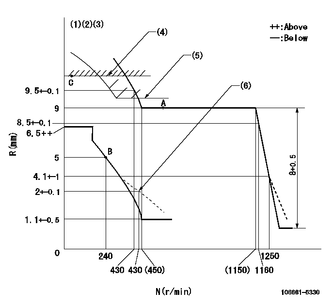
N:Pump speed
R:Rack position (mm)
(1)Lever ratio: RT
(2)Target shim dimension: TH
(3)Tolerance for racks not indicated: +-0.05mm.
(4)Rack limit using the stop lever: R1
(5)Excess fuel setting for starting: SXL (N = N1)
(6)Damper spring setting
----------
RT=1 TH=2.3mm R1=10.8+0.2mm SXL=9+0.2mm N1=400r/min
----------
----------
RT=1 TH=2.3mm R1=10.8+0.2mm SXL=9+0.2mm N1=400r/min
----------
Speed control lever angle

F:Full speed
----------
----------
a=21deg+-5deg
----------
----------
a=21deg+-5deg
0000000901

F:Full load
I:Idle
(1)Stopper bolt setting
----------
----------
a=15deg+-5deg b=29deg+-3deg
----------
----------
a=15deg+-5deg b=29deg+-3deg
Stop lever angle
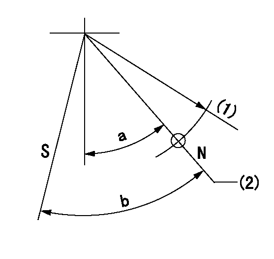
N:Pump normal
S:Stop the pump.
(1)R = aa
(2)Rack position bb
----------
aa=50mm bb=10.8+0.2mm
----------
a=26deg+-5deg b=28deg+-5deg
----------
aa=50mm bb=10.8+0.2mm
----------
a=26deg+-5deg b=28deg+-5deg
Timing setting

(1)Pump vertical direction
(2)Coupling's key groove position at No 1 cylinder's beginning of injection
(3)-
(4)-
----------
----------
a=(30deg)
----------
----------
a=(30deg)
Information:
This Program must be administered either before or after failure.In either case the decision whether to apply the Program is made by the dealer. When reporting the repair, use "PS42850" as the Part Numberand "7755" as the Group Number. If administered before failure, use "56" as the Warranty Claim Description Code and "T" as the SIMS Description code.If administered after failure, use "96" as the Warranty Claim Description Code, and "Z" as the SIMS Description Code.
The information supplied in this service letter may not be valid after the termination date of this program.Do not perform the work outlined in this Service Letter after the termination date without first contacting your Caterpillar product analyst.
TERMINATION DATE
31Dec2010
PROBLEM
The existing 153-8920 Injector Wire Harness can be too long on certain 3126B Engines. If the existing 153-8920 Injector Wire Harness fails it can cause the injectors to not function.
AFFECTED PRODUCT
Model Identification Number
DV-3304B BDZ01232, 1246-1248, 1250, 1253, 1256-1259, 1261, 1264-1274, 1276-1277, 1279-1283, 1286, 1292, 1294, 1299-1301, 1303-1315, 1340, 1349-1350, 1362, 1364, 1367, 1369, 1410, 1414-1415, 1417, 1421-1422, 1489, 1559, 1561-1563, 1572, 1574-1577, 1580-1586, 1591-1595, 1597-1610, 1612, 1614-1635, 1637, 1642-1648, 1650-1652, 1654-1680, 1686-1690, 1696-1698
PARTS NEEDED
Qty
Part Number Description
1 1538920 HARNESS AS.-WRG (As Required)
In order to allow equitable parts availability to all participating dealers, please limit your initial parts order to not exceed 18% of dealership population. This is an initial order recommendation only, and the ultimate responsibility for ordering the total number of parts needed to satisfy the program lies with the dealer.
ACTION REQUIRED
Refer to Disassembly and Assembly Manual SENR9589.
Remove the valve cover.
Inspect the injector wire harness. Ensure the injector wire harness does not interfere with the valve springs or other components.
Replace the injector wire harness if the harness is damaged.
SERVICE CLAIM ALLOWANCES
Product smu/age whichever comes first Caterpillar Dealer Suggested Customer Suggested
Parts % Labor Hrs% Parts % Labor Hrs% Parts % Labor Hrs%
0-500 hrs,
0-24 mo 100.0% 100.0% 0.0% 0.0% 0.0% 0.0%
This is a 0.5-hour job
If the injector wire harness needs to be replace, an extra 3 hours of labor is allowed.
PARTS DISPOSITION
Handle the parts in accordance with your Warranty Bulletin on warranty parts handling.
Have questions with 106661-5330?
Group cross 106661-5330 ZEXEL
Nissan-Diesel
Nissan-Diesel
Nissan-Diesel
106661-5330
INJECTION-PUMP ASSEMBLY