Information injection-pump assembly
BOSCH
9 400 616 616
9400616616
ZEXEL
106661-5293
1066615293
NISSAN-DIESEL
1671396761
1671396761
Rating:
Service parts 106661-5293 INJECTION-PUMP ASSEMBLY:
1.
_
7.
COUPLING PLATE
8.
_
9.
_
11.
Nozzle and Holder
1660096508
12.
Open Pre:MPa(Kqf/cm2)
19.6(200)

15.
NOZZLE SET
Include in #1:
106661-5293
as INJECTION-PUMP ASSEMBLY
Cross reference number
BOSCH
9 400 616 616
9400616616
ZEXEL
106661-5293
1066615293
NISSAN-DIESEL
1671396761
1671396761
Zexel num
Bosch num
Firm num
Name
106661-5293
9 400 616 616
1671396761 NISSAN-DIESEL
INJECTION-PUMP ASSEMBLY
PE6 * K
PE6 * K
Calibration Data:
Adjustment conditions
Test oil
1404 Test oil ISO4113 or {SAEJ967d}
1404 Test oil ISO4113 or {SAEJ967d}
Test oil temperature
degC
40
40
45
Nozzle and nozzle holder
105780-8140
Bosch type code
EF8511/9A
Nozzle
105780-0000
Bosch type code
DN12SD12T
Nozzle holder
105780-2080
Bosch type code
EF8511/9
Opening pressure
MPa
17.2
Opening pressure
kgf/cm2
175
Injection pipe
Outer diameter - inner diameter - length (mm) mm 8-3-600
Outer diameter - inner diameter - length (mm) mm 8-3-600
Overflow valve opening pressure
kPa
157
123
191
Overflow valve opening pressure
kgf/cm2
1.6
1.25
1.95
Tester oil delivery pressure
kPa
157
157
157
Tester oil delivery pressure
kgf/cm2
1.6
1.6
1.6
Direction of rotation (viewed from drive side)
Right R
Right R
Injection timing adjustment
Direction of rotation (viewed from drive side)
Right R
Right R
Injection order
1-4-2-6-
3-5
Pre-stroke
mm
3.65
3.6
3.7
Beginning of injection position
Drive side NO.1
Drive side NO.1
Difference between angles 1
Cal 1-4 deg. 60 59.5 60.5
Cal 1-4 deg. 60 59.5 60.5
Difference between angles 2
Cyl.1-2 deg. 120 119.5 120.5
Cyl.1-2 deg. 120 119.5 120.5
Difference between angles 3
Cal 1-6 deg. 180 179.5 180.5
Cal 1-6 deg. 180 179.5 180.5
Difference between angles 4
Cal 1-3 deg. 240 239.5 240.5
Cal 1-3 deg. 240 239.5 240.5
Difference between angles 5
Cal 1-5 deg. 300 299.5 300.5
Cal 1-5 deg. 300 299.5 300.5
Injection quantity adjustment
Adjusting point
A
Rack position
12.2
Pump speed
r/min
750
750
750
Average injection quantity
mm3/st.
122.3
120.3
124.3
Max. variation between cylinders
%
0
-4
4
Basic
*
Fixing the lever
*
Injection quantity adjustment_02
Adjusting point
B
Rack position
12
Pump speed
r/min
500
500
500
Average injection quantity
mm3/st.
102.2
99.2
105.2
Max. variation between cylinders
%
0
-4
4
Fixing the lever
*
Injection quantity adjustment_03
Adjusting point
-
Rack position
7+-0.5
Pump speed
r/min
240
240
240
Average injection quantity
mm3/st.
10
8.7
11.3
Max. variation between cylinders
%
0
-10
10
Fixing the rack
*
Remarks
Adjust only variation between cylinders; adjust governor according to governor specifications.
Adjust only variation between cylinders; adjust governor according to governor specifications.
Injection quantity adjustment_04
Adjusting point
D
Rack position
6.8+-0.5
Pump speed
r/min
275
275
275
Average injection quantity
mm3/st.
8
6
10
Fixing the lever
*
Timer adjustment
Pump speed
r/min
200+100
Advance angle
deg.
1.6
1.1
2.1
Remarks
Start
Start
Timer adjustment_02
Pump speed
r/min
500-150
Advance angle
deg.
0
0
0
Timer adjustment_03
Pump speed
r/min
925+-30
Advance angle
deg.
0
0
0
Timer adjustment_04
Pump speed
r/min
1100
Advance angle
deg.
3
2.5
3.5
Remarks
Finish
Finish
Test data Ex:
Governor adjustment
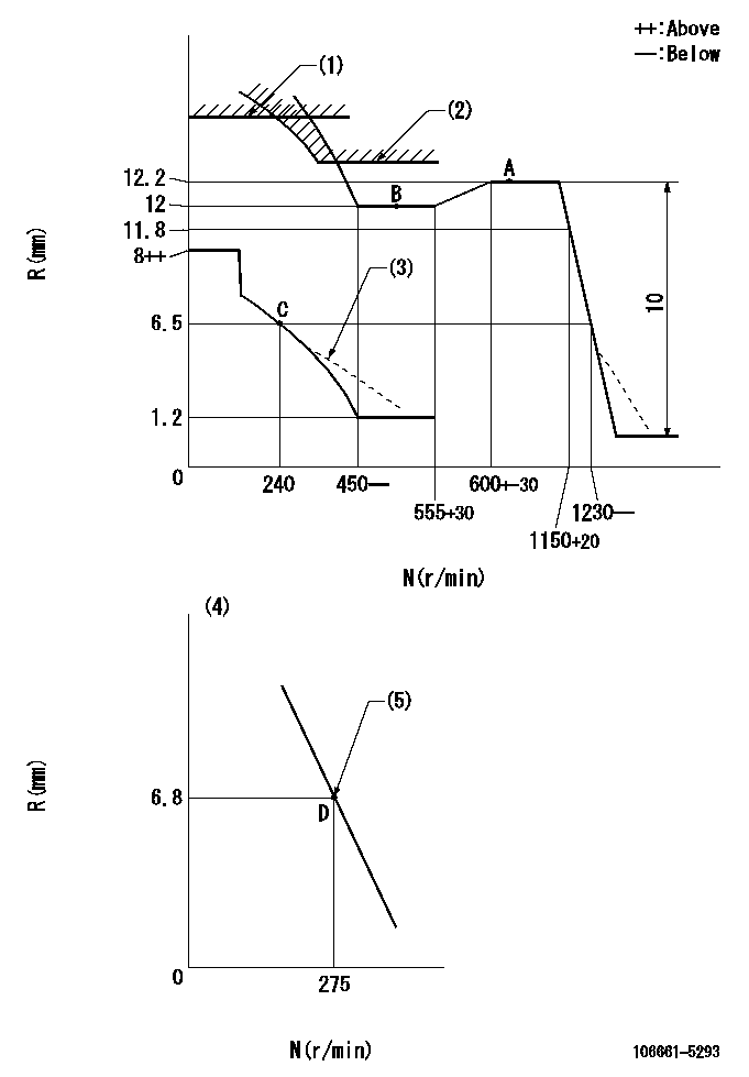
N:Pump speed
R:Rack position (mm)
(1)Rack limit using the stop lever: R1
(2)Excess fuel setting for starting: SXL
(3)Damper spring setting: DL
(4)Variable speed specification: idling adjustment
(5)Main spring setting
----------
R1=14+-0.1mm SXL=12.2+0.2mm DL=5.5-0.5mm
----------
----------
R1=14+-0.1mm SXL=12.2+0.2mm DL=5.5-0.5mm
----------
Speed control lever angle
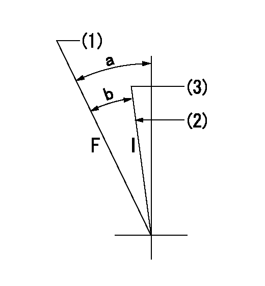
F:Full speed
I:Idle
(1)Set the pump speed at aa
(2)Stopper bolt setting
(3)Set the pump speed at bb.
----------
aa=1150r/min bb=275r/min
----------
a=31deg+-5deg b=23deg+-5deg
----------
aa=1150r/min bb=275r/min
----------
a=31deg+-5deg b=23deg+-5deg
0000000901

F:Full load
I:Idle
(1)Stopper bolt setting
----------
----------
a=15deg+-5deg b=39deg+-3deg
----------
----------
a=15deg+-5deg b=39deg+-3deg
Stop lever angle
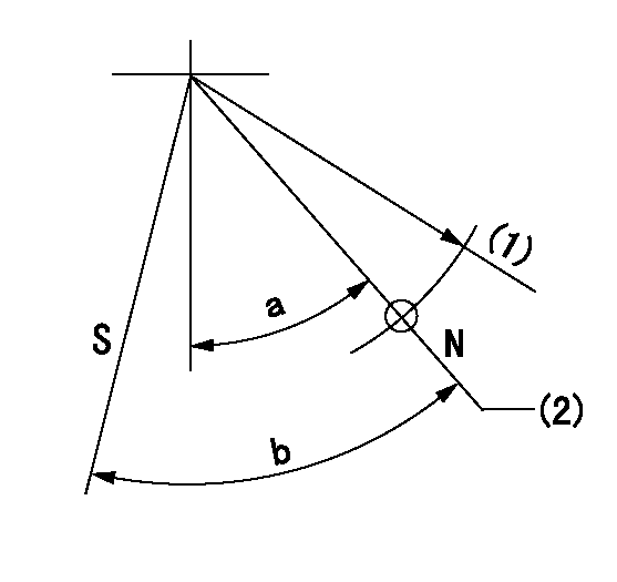
N:Pump normal
S:Stop the pump.
(1)R = aa
(2)Rack position bb
----------
aa=50mm bb=14+-0.1mm
----------
a=34.5deg+-5deg b=36.5deg+-3deg
----------
aa=50mm bb=14+-0.1mm
----------
a=34.5deg+-5deg b=36.5deg+-3deg
Timing setting

(1)Pump vertical direction
(2)Coupling's key groove position at No 1 cylinder's beginning of injection
(3)-
(4)-
----------
----------
a=(30deg)
----------
----------
a=(30deg)
Information:
Image1.1.1
4) Remove the 90 degree pressure line fitting under the sensor box.
5) Remove the 90 degree pressure line fitting from the DPF center section that is closest to the outlet side.
6) The new pressure line that will fit into the DPF center section will need to be installed into the port in which the thermocouple was fitted. The existing thermocouple will need to be fitted into the port in which the old pressure line was fitted.
Swapping of the ports is only necessary on the outlet side of the center section.
Image1.2.1
Image1.2.2
7) Install the 7W-3556 washer on the 304-8042 straight fitting. Install the straight fitting into the DPF pressure port (towards the outlet side) in which the thermocouple was previously installed, tighten to a torque of 24 +/- 4 Nm (212 +/- 35 lb-in). Screw the 2N-8142 tee fitting onto that straight fitting and tighten to a torque of 24 +/- 4 Nm (212 +/- 35 lb-in).
Image1.3.1
8) Replace the O-ring on the sensor box where the old 90 degree pressure line fitting was located. Install the 4S-4857 tee fitting in the sensor box to a torque of 11 +/- 1 Nm (97 +/- 9 lb-in).
Image1.4.1
9) Where applicable, perform Service Letter REBE3391 at this time.
10) Install sensor box bracket and existing heat shield. Tighten all six bolts to a torque of 12 +/- 3 Nm (106 +/- 27 lb-in).
11) Install sensor box, new pressure lines (tube assemblies), thermocouples onto DPF, and cable straps.
Reference appropriate Disassembly and Assembly manual for proper torque and use of anti-seize.
Image1.5.1
12) Start the engine and use CAT ET to ensure that the status parameter Diesel Particulate Trap #1 Differential Pressure has a value greater than zero. Also, ensure status parameters Diesel Particulate Trap #1 Intake Temperature, and Diesel Particulate Trap #1 Outlet Temperature show reasonable values and increase with the rising exhaust temperatures.
Have questions with 106661-5293?
Group cross 106661-5293 ZEXEL
Nissan-Diesel
Nissan-Diesel
Nissan-Diesel
Nissan-Diesel
Nissan-Diesel
Nissan-Diesel
Nissan-Diesel
Nissan-Diesel
106661-5293
9 400 616 616
1671396761
INJECTION-PUMP ASSEMBLY
PE6
PE6