Information injection-pump assembly
ZEXEL
106661-5270
1066615270

Rating:
Service parts 106661-5270 INJECTION-PUMP ASSEMBLY:
1.
_
7.
COUPLING PLATE
8.
_
9.
_
11.
Nozzle and Holder
1660096502
12.
Open Pre:MPa(Kqf/cm2)
22.6(230)
15.
NOZZLE SET
Include in #1:
106661-5270
as INJECTION-PUMP ASSEMBLY
Cross reference number
ZEXEL
106661-5270
1066615270
Zexel num
Bosch num
Firm num
Name
106661-5270
INJECTION-PUMP ASSEMBLY
Calibration Data:
Adjustment conditions
Test oil
1404 Test oil ISO4113 or {SAEJ967d}
1404 Test oil ISO4113 or {SAEJ967d}
Test oil temperature
degC
40
40
45
Nozzle and nozzle holder
105780-8140
Bosch type code
EF8511/9A
Nozzle
105780-0000
Bosch type code
DN12SD12T
Nozzle holder
105780-2080
Bosch type code
EF8511/9
Opening pressure
MPa
17.2
Opening pressure
kgf/cm2
175
Injection pipe
Outer diameter - inner diameter - length (mm) mm 8-3-600
Outer diameter - inner diameter - length (mm) mm 8-3-600
Overflow valve opening pressure
kPa
157
123
191
Overflow valve opening pressure
kgf/cm2
1.6
1.25
1.95
Tester oil delivery pressure
kPa
157
157
157
Tester oil delivery pressure
kgf/cm2
1.6
1.6
1.6
Direction of rotation (viewed from drive side)
Right R
Right R
Injection timing adjustment
Direction of rotation (viewed from drive side)
Right R
Right R
Injection order
1-4-2-6-
3-5
Pre-stroke
mm
3.2
3.15
3.25
Beginning of injection position
Drive side NO.1
Drive side NO.1
Difference between angles 1
Cal 1-4 deg. 60 59.5 60.5
Cal 1-4 deg. 60 59.5 60.5
Difference between angles 2
Cyl.1-2 deg. 120 119.5 120.5
Cyl.1-2 deg. 120 119.5 120.5
Difference between angles 3
Cal 1-6 deg. 180 179.5 180.5
Cal 1-6 deg. 180 179.5 180.5
Difference between angles 4
Cal 1-3 deg. 240 239.5 240.5
Cal 1-3 deg. 240 239.5 240.5
Difference between angles 5
Cal 1-5 deg. 300 299.5 300.5
Cal 1-5 deg. 300 299.5 300.5
Injection quantity adjustment
Adjusting point
A
Rack position
12.3
Pump speed
r/min
750
750
750
Average injection quantity
mm3/st.
153.1
151.1
155.1
Max. variation between cylinders
%
0
-4
4
Basic
*
Fixing the lever
*
Injection quantity adjustment_02
Adjusting point
B
Rack position
11.3
Pump speed
r/min
750
750
750
Average injection quantity
mm3/st.
135.2
133.2
137.2
Max. variation between cylinders
%
0
-4
4
Fixing the lever
*
Injection quantity adjustment_03
Adjusting point
C
Rack position
6.7+-0.5
Pump speed
r/min
300
300
300
Average injection quantity
mm3/st.
12.2
11.2
13.2
Max. variation between cylinders
%
0
-10
10
Fixing the rack
*
Timer adjustment
Pump speed
r/min
400--
Advance angle
deg.
0
0
0
Remarks
Start
Start
Timer adjustment_02
Pump speed
r/min
350
Advance angle
deg.
0.5
Timer adjustment_03
Pump speed
r/min
900
Advance angle
deg.
2.5
2
3
Timer adjustment_04
Pump speed
r/min
-
Advance angle
deg.
4
4
4
Remarks
Measure the actual speed, stop
Measure the actual speed, stop
Test data Ex:
Governor adjustment
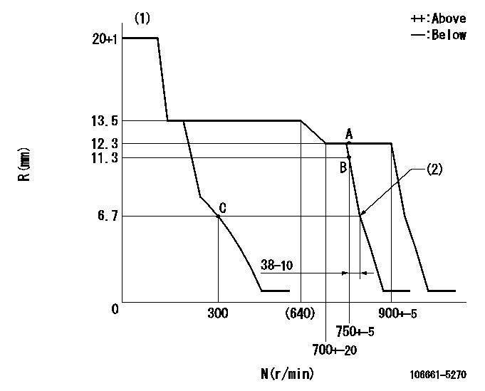
N:Pump speed
R:Rack position (mm)
(1)Target notch: K
(2)Idle sub spring setting: L1.
----------
K=13 L1=6.7-0.5mm
----------
----------
K=13 L1=6.7-0.5mm
----------
Speed control lever angle
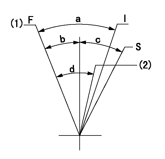
F:Full speed
I:Idle
S:Stop
(1)Speed set at aa (setting at shipping)
(2)Set the pump speed at bb.
----------
aa=900r/min bb=750r/min
----------
a=27deg+-5deg b=5deg+-5deg c=32deg+-3deg d=7deg+-5deg
----------
aa=900r/min bb=750r/min
----------
a=27deg+-5deg b=5deg+-5deg c=32deg+-3deg d=7deg+-5deg
Stop lever angle

N:Pump normal
S:Stop the pump.
----------
----------
a=26deg+-5deg b=53deg+-5deg
----------
----------
a=26deg+-5deg b=53deg+-5deg
0000001501 GOV FULL LOAD ADJUSTMENT
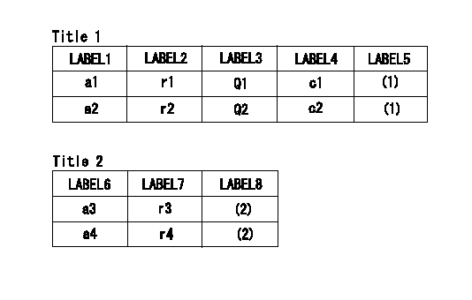
Title1:Full load stopper adjustment
Title2:Governor set speed
LABEL1:Distinguishing
LABEL2:Pump speed (r/min)
LABEL3:Ave. injection quantity (mm3/st)
LABEL4:Max. var. bet. cyl.
LABEL5:Remarks
LABEL6:Distinguishing
LABEL7:Governor set speed (r/min)
LABEL8:Remarks
(1)Adjustment conditions are the same as those for measuring injection quantity.
(2)-
----------
----------
a1=A a2=E r1=750r/min r2=750r/min Q1=153.1+-2mm3/st Q2=197.5+-2mm3/st c1=+-4% c2=+-4% a3=18 a4=15 r3=900r/min r4=750r/min
----------
----------
a1=A a2=E r1=750r/min r2=750r/min Q1=153.1+-2mm3/st Q2=197.5+-2mm3/st c1=+-4% c2=+-4% a3=18 a4=15 r3=900r/min r4=750r/min
Information:
Illustration 1 g06140436
(1) 277-7637 Bracket
(2) 8T-3490 Weld NutWeld the 8T-3490 Weld Nut (2) on the 277-7637 Bracket (1) as shown in Illustration 1.
Illustration 2 g06140437
Weld location
Illustration 3 g06140439
View of area A
(1) Welded bracket
Illustration 4 g06140464
(B) 10 mm (0.4 inch)
(C) 36 mm (1.4 inch)
(E) 27 mm (1.1 inch)
(W1) 3 mm (0.1 inch) Fillet weldWeld the 277-7637 Bracket (1) on the frame as shown in Illustration 4.CEM Hose Removal and Install Procedure
Illustration 5 g06140472
(3) 418-2057 Hose
(4) 418-2055 HoseRemove the 418-2057 Hose (3) and the 418-2055 Hose (4).
Illustration 6 g06140489
(5) 428-8808 Hose Clamp
(6) 468-4707 Hose
(7) 326-4516 Cable Tie
(8) 468-4709 Hose
(9) 449-2092 Hose
(10) 428-8808 Hose Clamp
Assemble the 468-4707 Hose (6), the 468-4709 Hose (8), and the 449-2092 Hose (9) as shown in Illustration 6.
Secure the 468-4707 Hose (6) with a 326-4516 Cable Tie (7)
Tighten the two 428-8808 Hose Clamps (5) to 6.5 to 6.8 N m (58 to 60 lb in).
Tighten the four 428-8808 Hose Clamps (10) to 6.5 to 6.8 N m (58 to 60 lb in) and install hose clamp same as original hose clamp position before the rework.374F Phase Change Tank
Illustration 7 g06140762
(11) 8T-4189 Bolt
(12) 8T-4224 Hard Washer
(13) 357-4586 Elbow As
(F) 30 degree
Tighten the 8T-4189 Bolt (11) to 28 7 N m (248 62 lb in).
Assemble the 357-4586 Elbow As (13) at an angle 30 degree (F) as shown in Illustration 7 and tighten to 28 4 N m (248 35 lb in).390F Phase Change Tank
Illustration 8 g06140765
(11) 8T-4189 Bolt
(12) 8T-4224 Hard Washer
(13) 357-4586 Elbow As
(14) 468-4722 Plate As
(F) 30 degreePhase change tank and related parts are same as 374F. The difference is only support plate 468-4722 Plate As (14). Repeat the Step 1 and Step 2.Support Plate Mount
Illustration 9 g06140788
(15) 8T-4137 Bolt
(16) 7X-7729 Washer
(17) 135-8575 Bolt As (Reuse)Illustration 9 is showing example for the 374F. The different bracket is used on the 390F however the procedure is same.
Tighten the 8T-4137 Bolt (15) to 100 20 N m (74 15 lb ft).
Tighten the 135-8575 Bolt As (17) to 100 20 N m (74 15 lb ft).Software
Download the latest software from SIS Web. Refer Illustration 10 for flash software download.
Illustration 10 g06140790Tune Value Update
Illustration 11 g06140791Update threshold to 525 °C using Cat Electronic Technician (Cat ET) as shown in Illustration 11. Factory password is required to change the value. When you input your CWS ID, the factory password can be provided.
Have questions with 106661-5270?
Group cross 106661-5270 ZEXEL
Nissan-Diesel
Nissan-Diesel
Nissan-Diesel
Nissan-Diesel
Nissan-Diesel
Nissan-Diesel
106661-5270
INJECTION-PUMP ASSEMBLY