Information injection-pump assembly
ZEXEL
106661-4042
1066614042
Rating:
Service parts 106661-4042 INJECTION-PUMP ASSEMBLY:
1.
_
7.
COUPLING PLATE
8.
_
9.
_
10.
NOZZLE AND HOLDER ASSY
11.
Nozzle and Holder
12.
Open Pre:MPa(Kqf/cm2)
13.
NOZZLE-HOLDER
14.
NOZZLE
15.
NOZZLE SET
Include in #1:
106661-4042
as INJECTION-PUMP ASSEMBLY
Cross reference number
ZEXEL
106661-4042
1066614042
Zexel num
Bosch num
Firm num
Name
106661-4042
INJECTION-PUMP ASSEMBLY
Calibration Data:
Adjustment conditions
Test oil
1404 Test oil ISO4113 or {SAEJ967d}
1404 Test oil ISO4113 or {SAEJ967d}
Test oil temperature
degC
40
40
45
Nozzle and nozzle holder
105780-8140
Bosch type code
EF8511/9A
Nozzle
105780-0000
Bosch type code
DN12SD12T
Nozzle holder
105780-2080
Bosch type code
EF8511/9
Opening pressure
MPa
17.2
Opening pressure
kgf/cm2
175
Injection pipe
Outer diameter - inner diameter - length (mm) mm 8-3-600
Outer diameter - inner diameter - length (mm) mm 8-3-600
Overflow valve
131424-1520
Overflow valve opening pressure
kPa
157
123
191
Overflow valve opening pressure
kgf/cm2
1.6
1.25
1.95
Tester oil delivery pressure
kPa
157
157
157
Tester oil delivery pressure
kgf/cm2
1.6
1.6
1.6
Direction of rotation (viewed from drive side)
Right R
Right R
Injection timing adjustment
Direction of rotation (viewed from drive side)
Right R
Right R
Injection order
1-4-2-6-
3-5
Pre-stroke
mm
4.2
4.15
4.25
Beginning of injection position
Drive side NO.1
Drive side NO.1
Difference between angles 1
Cal 1-4 deg. 60 59.5 60.5
Cal 1-4 deg. 60 59.5 60.5
Difference between angles 2
Cyl.1-2 deg. 120 119.5 120.5
Cyl.1-2 deg. 120 119.5 120.5
Difference between angles 3
Cal 1-6 deg. 180 179.5 180.5
Cal 1-6 deg. 180 179.5 180.5
Difference between angles 4
Cal 1-3 deg. 240 239.5 240.5
Cal 1-3 deg. 240 239.5 240.5
Difference between angles 5
Cal 1-5 deg. 300 299.5 300.5
Cal 1-5 deg. 300 299.5 300.5
Injection quantity adjustment
Adjusting point
A
Rack position
12.3
Pump speed
r/min
1350
1350
1350
Each cylinder's injection qty
mm3/st.
182
178.4
185.6
Basic
*
Fixing the lever
*
Boost pressure
kPa
60
60
Boost pressure
mmHg
450
450
Injection quantity adjustment_02
Adjusting point
B
Rack position
7.5+-0.5
Pump speed
r/min
225
225
225
Each cylinder's injection qty
mm3/st.
27.8
24.3
31.3
Fixing the rack
*
Boost pressure
kPa
0
0
0
Boost pressure
mmHg
0
0
0
Injection quantity adjustment_03
Adjusting point
C
Rack position
-
Pump speed
r/min
100
100
100
Average injection quantity
mm3/st.
214
209
219
Fixing the lever
*
Boost pressure
kPa
0
0
0
Boost pressure
mmHg
0
0
0
Rack limit
*
Boost compensator adjustment
Pump speed
r/min
500
500
500
Rack position
R1-2.1
Boost pressure
kPa
13.3
10.6
16
Boost pressure
mmHg
100
80
120
Boost compensator adjustment_02
Pump speed
r/min
500
500
500
Rack position
R1(12.3)
Boost pressure
kPa
46.7
40
53.4
Boost pressure
mmHg
350
300
400
Timer adjustment
Pump speed
r/min
450--
Advance angle
deg.
0
0
0
Remarks
Start
Start
Timer adjustment_02
Pump speed
r/min
400
Advance angle
deg.
0.5
Timer adjustment_03
Pump speed
r/min
1100
Advance angle
deg.
2.5
2
3
Remarks
Finish
Finish
Test data Ex:
Governor adjustment
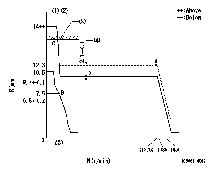
N:Pump speed
R:Rack position (mm)
(1)Target notch: K
(2)Tolerance for racks not indicated: +-0.05mm.
(3)RACK LIMIT
(4)Boost compensator stroke
----------
K=10
----------
----------
K=10
----------
Speed control lever angle
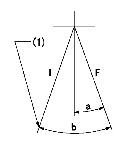
F:Full speed
I:Idle
(1)Stopper bolt setting
----------
----------
a=13deg+-5deg b=28deg+-5deg
----------
----------
a=13deg+-5deg b=28deg+-5deg
Stop lever angle

N:Pump normal
S:Stop the pump.
(1)Pump speed aa and rack position bb (to be sealed at delivery)
----------
aa=0r/min bb=1-0.5mm
----------
a=25deg+-5deg b=70deg+-5deg
----------
aa=0r/min bb=1-0.5mm
----------
a=25deg+-5deg b=70deg+-5deg
Timing setting

(1)Pump vertical direction
(2)Coupling's key groove position for the No. 6 cylinder's beginning of injection
(3)-
(4)-
----------
----------
a=(120deg)
----------
----------
a=(120deg)
Information:
Operations that may cause product damage are identified by notice labels in this publication.
Introduction
This Tool Operating Manual contains two filter installation procedures. This first procedure is for installing a primary filter system. This is a coarse filter and will protect the transfer pump from contamination in the oil. The second procedure outlines installing a secondary filter which is designed to protect injection pumps from contaminated oil. Fuel injection pumps used on the 3208 Engine are one example of a fuel injection pump that requires the secondary filter installation.It will be the dealer choice as to which optional filter is installed on the test stand. Determine what type of filtering will be required most often, and install the appropriate type of filtering system. These filters can only be added to the 15 horsepower test stands.Secondary Filter
Nomenclature
Illustration 1. Nomenclature for Secondary Filter Installation. Refer to Chart A for item identification. Fabricated Parts
All the parts required for this installation can be ordered from Caterpillar Parts Distribution, except bracket (1). This must be manufactured by the bench owner, using the dimensions provided below.This bracket can be made from common SAE1018 steel. Weld the two pieces together.
Illustration 2. Filter Mounting Bracket. Refer to Chart B for dimensions. Installation
Assemble the Fuel Filter
1. Install 053-0088 Fitting (17) with 3J-1907 Seal (18) into the inlet port (left side) of the filter base. (This converts a number 6 STOP port to NPT). Install 5P-4455 Fitting (19) into fitting (17).2. Install 2R-6806 Fitting (15) with 3J-1907 Seal (16) into the outlet port (right side) of the filter base.3. Install 6N-4414 Cover (7) onto the filter base using 1P-0436 Gasket (8), 4B-3388/6V-2317 (9), and OS-1616/6V-8490 Bolt (10).4. Install 9S-4182 Plug (5) with 6V-5084 O-ring Seal (6) into the top of the filter base.5. Install the filter base assembly onto filter bracket (1),
Have questions with 106661-4042?
Group cross 106661-4042 ZEXEL
Daihatsu
Daihatsu
Yanmar
106661-4042
INJECTION-PUMP ASSEMBLY