Information injection-pump assembly
ZEXEL
106661-4041
1066614041
YANMAR
12769151010
12769151010
Rating:
Service parts 106661-4041 INJECTION-PUMP ASSEMBLY:
1.
_
7.
COUPLING PLATE
8.
_
9.
_
10.
NOZZLE AND HOLDER ASSY
11.
Nozzle and Holder
12.
Open Pre:MPa(Kqf/cm2)
13.
NOZZLE-HOLDER
14.
NOZZLE
15.
NOZZLE SET
Include in #1:
106661-4041
as INJECTION-PUMP ASSEMBLY
Cross reference number
ZEXEL
106661-4041
1066614041
YANMAR
12769151010
12769151010
Zexel num
Bosch num
Firm num
Name
Calibration Data:
Adjustment conditions
Test oil
1404 Test oil ISO4113 or {SAEJ967d}
1404 Test oil ISO4113 or {SAEJ967d}
Test oil temperature
degC
40
40
45
Nozzle and nozzle holder
105780-8140
Bosch type code
EF8511/9A
Nozzle
105780-0000
Bosch type code
DN12SD12T
Nozzle holder
105780-2080
Bosch type code
EF8511/9
Opening pressure
MPa
17.2
Opening pressure
kgf/cm2
175
Injection pipe
Outer diameter - inner diameter - length (mm) mm 8-3-600
Outer diameter - inner diameter - length (mm) mm 8-3-600
Overflow valve
131424-1520
Overflow valve opening pressure
kPa
157
123
191
Overflow valve opening pressure
kgf/cm2
1.6
1.25
1.95
Tester oil delivery pressure
kPa
157
157
157
Tester oil delivery pressure
kgf/cm2
1.6
1.6
1.6
Direction of rotation (viewed from drive side)
Right R
Right R
Injection timing adjustment
Direction of rotation (viewed from drive side)
Right R
Right R
Injection order
1-4-2-6-
3-5
Pre-stroke
mm
4.2
4.15
4.25
Beginning of injection position
Drive side NO.1
Drive side NO.1
Difference between angles 1
Cal 1-4 deg. 60 59.5 60.5
Cal 1-4 deg. 60 59.5 60.5
Difference between angles 2
Cyl.1-2 deg. 120 119.5 120.5
Cyl.1-2 deg. 120 119.5 120.5
Difference between angles 3
Cal 1-6 deg. 180 179.5 180.5
Cal 1-6 deg. 180 179.5 180.5
Difference between angles 4
Cal 1-3 deg. 240 239.5 240.5
Cal 1-3 deg. 240 239.5 240.5
Difference between angles 5
Cal 1-5 deg. 300 299.5 300.5
Cal 1-5 deg. 300 299.5 300.5
Injection quantity adjustment
Adjusting point
A
Rack position
10.6
Pump speed
r/min
1350
1350
1350
Each cylinder's injection qty
mm3/st.
182
178.4
185.6
Basic
*
Fixing the lever
*
Boost pressure
kPa
60
60
Boost pressure
mmHg
450
450
Injection quantity adjustment_02
Adjusting point
B
Rack position
6.7+-0.5
Pump speed
r/min
225
225
225
Each cylinder's injection qty
mm3/st.
27.8
24.3
31.3
Fixing the rack
*
Boost pressure
kPa
0
0
0
Boost pressure
mmHg
0
0
0
Injection quantity adjustment_03
Adjusting point
C
Rack position
-
Pump speed
r/min
100
100
100
Average injection quantity
mm3/st.
214
209
219
Fixing the lever
*
Boost pressure
kPa
0
0
0
Boost pressure
mmHg
0
0
0
Rack limit
*
Boost compensator adjustment
Pump speed
r/min
500
500
500
Rack position
R1-2.1
Boost pressure
kPa
13.3
10.6
16
Boost pressure
mmHg
100
80
120
Boost compensator adjustment_02
Pump speed
r/min
500
500
500
Rack position
R1(10.6)
Boost pressure
kPa
46.7
40
53.4
Boost pressure
mmHg
350
300
400
Timer adjustment
Pump speed
r/min
450--
Advance angle
deg.
0
0
0
Remarks
Start
Start
Timer adjustment_02
Pump speed
r/min
400
Advance angle
deg.
0.5
Timer adjustment_03
Pump speed
r/min
1100
Advance angle
deg.
2.5
2
3
Remarks
Finish
Finish
Test data Ex:
Governor adjustment
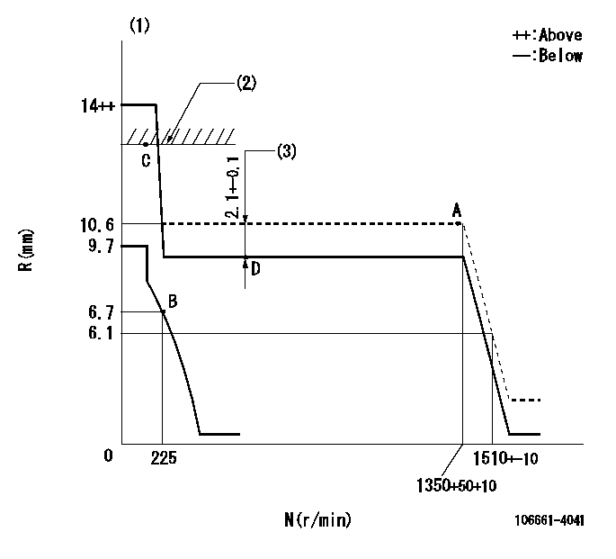
N:Pump speed
R:Rack position (mm)
(1)Target notch: K
(2)RACK LIMIT
(3)Boost compensator stroke
----------
K=14
----------
----------
K=14
----------
Speed control lever angle
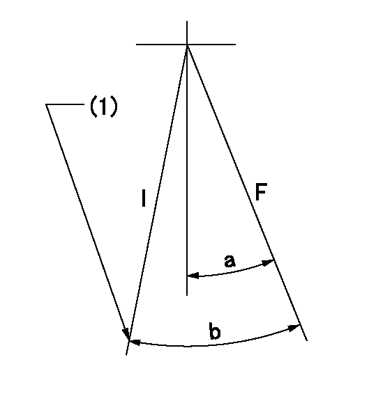
F:Full speed
I:Idle
(1)Stopper bolt setting
----------
----------
a=17deg+-5deg b=30deg+-5deg
----------
----------
a=17deg+-5deg b=30deg+-5deg
Stop lever angle

N:Pump normal
S:Stop the pump.
(1)Pump speed aa and rack position bb (to be sealed at delivery)
----------
aa=0r/min bb=1-0.2mm
----------
a=25deg+-5deg b=70deg+-5deg
----------
aa=0r/min bb=1-0.2mm
----------
a=25deg+-5deg b=70deg+-5deg
Timing setting

(1)Pump vertical direction
(2)Coupling's key groove position for the No. 6 cylinder's beginning of injection
(3)-
(4)-
----------
----------
a=(120deg)
----------
----------
a=(120deg)
Information:
3406B and 3406C Non-Peec Engines
Steps 4 through 7 do not apply to PEEC engines.
Illustration 16. Install Lever Assembly
(1) 6N-3646 Lever. (2) 5P-0537 Washer. (3) 6V-8918 Bolt. (4) 9M-3858 Rack Preload Spring. (5) 1B-7182 Bolt.4. Install lever (1) with washer (2) and bolt (3).5. Install bolt (5) into hole as shown.6. Hook spring (4) between bolt (5) and lever (1).
Illustration 17. Install Rack Positioning Assembly
(1) 9U-5296 Rack Assembly. (2) Original cover mounting bolts or 4F-7957 Bolt.7. Install rack positioning assembly (1) with bolts (2). Use rack positioning assembly (1) as a "fuel ON" and "fuel OFF" control. Position the assembly to the full "fuel ON" position for all tests. Use the positioning assembly for rack adjustment.3406 Peec Engines
Steps 8 and 9 do not apply to Non-PEEC engines.
Illustration 18. Installing testing hardware for 3406 PEEC Engines
(1) 9U-5292 Rack Preload Assembly. (2) 9U-5120 Spanner Wrench. (3) 9U-5295 Positioning Assembly.8. Remove the BTM from the injection pump and install the 9U-5292 Rack Preload Assembly (1). Make sure the pin is properly located in the slot of the servo shaft. After installing the rack preload assembly, finger tighten the bolts.9. Remove the shut-off solenoid with a 9U-5120 Spanner Wrench (2) and install 9U-5295 Positioning Assembly (3). Use rack preload assembly (1) as a "fuel ON" and "fuel OFF" control. Position the assembly to the full "fuel ON" position for all tests. Use the positioning assembly for rack adjustment.Connect Hoses and Lines
Illustration 19. Connect Lube Oil Supply and Drain Hose
(1) 7G-7105 Hose. (2) 5P-6661 Fitting. (3) 9U-7709 Oil Drain Tube and two 5D-1026 Hose Clamps.
Illustration 20. Connect Fuel Supply and Return Lines
(4) 030-7947 Fitting, 3J-1907 O-ring Seal, and 7G-7105 Hose. (5) 8T-2160 Orifice Fitting, 3J-1907 O-ring Seal, and 7G-7105 Hose. (6) 9U-5298 Fuel Injection Line Tube Assembly (verify fuel line part number in TMI).1. Attach one end of hose (1) to the Lube Oil Supply fitting on the test stand. Attach the other end to the 5P-6661 Fitting on the rear support.2. Connect the oil drain tube (2) to the rear support and the test stand's stand-pipe with two hose clamps. On the AVM20-12C, the drain hose can be routed to the lube oil drain pan.3. Install fitting, O-ring, and hose (4) onto the fuel injection pump. Connect the other end of the hose to the "Test Oil Supply" connection on the test stand.4. Install fitting, O-ring, and hose (5) onto the fuel injection pump. Connect the other end of the hose to the "Test Oil Return" connection on the test stand.
Hold nut on 9U-6705 Master Nozzle when tightening fuel injection line tube assemblies (6). If the nut is not held in place during tightening, the master nozzle can be damaged.
5. Install six fuel injection line tube assemblies (6).Pre-Test Checks
1. Remove the lock-out on the electrical box, if installed.2. Release the Emergency Stop button.3. Start the bench and visually check for oil leaks from covers, hoses, etc.4. Check for oil flow through the drain tube. Also, check for oil flowing out of the oil