Information injection-pump assembly
BOSCH
F 019 Z10 623
f019z10623
ZEXEL
106661-4040
1066614040
Rating:
Service parts 106661-4040 INJECTION-PUMP ASSEMBLY:
1.
_
7.
COUPLING PLATE
8.
_
9.
_
10.
NOZZLE AND HOLDER ASSY
11.
Nozzle and Holder
12.
Open Pre:MPa(Kqf/cm2)
13.
NOZZLE-HOLDER
14.
NOZZLE
15.
NOZZLE SET
Include in #1:
106661-4040
as INJECTION-PUMP ASSEMBLY
Cross reference number
BOSCH
F 019 Z10 623
f019z10623
ZEXEL
106661-4040
1066614040
Zexel num
Bosch num
Firm num
Name
Calibration Data:
Adjustment conditions
Test oil
1404 Test oil ISO4113 or {SAEJ967d}
1404 Test oil ISO4113 or {SAEJ967d}
Test oil temperature
degC
40
40
45
Nozzle and nozzle holder
105780-8140
Bosch type code
EF8511/9A
Nozzle
105780-0000
Bosch type code
DN12SD12T
Nozzle holder
105780-2080
Bosch type code
EF8511/9
Opening pressure
MPa
17.2
Opening pressure
kgf/cm2
175
Injection pipe
Outer diameter - inner diameter - length (mm) mm 8-3-600
Outer diameter - inner diameter - length (mm) mm 8-3-600
Overflow valve
132424-0620
Overflow valve opening pressure
kPa
157
123
191
Overflow valve opening pressure
kgf/cm2
1.6
1.25
1.95
Tester oil delivery pressure
kPa
157
157
157
Tester oil delivery pressure
kgf/cm2
1.6
1.6
1.6
Direction of rotation (viewed from drive side)
Right R
Right R
Injection timing adjustment
Direction of rotation (viewed from drive side)
Right R
Right R
Injection order
1-4-2-6-
3-5
Pre-stroke
mm
4.2
4.15
4.25
Beginning of injection position
Drive side NO.1
Drive side NO.1
Difference between angles 1
Cal 1-4 deg. 60 59.5 60.5
Cal 1-4 deg. 60 59.5 60.5
Difference between angles 2
Cyl.1-2 deg. 120 119.5 120.5
Cyl.1-2 deg. 120 119.5 120.5
Difference between angles 3
Cal 1-6 deg. 180 179.5 180.5
Cal 1-6 deg. 180 179.5 180.5
Difference between angles 4
Cal 1-3 deg. 240 239.5 240.5
Cal 1-3 deg. 240 239.5 240.5
Difference between angles 5
Cal 1-5 deg. 300 299.5 300.5
Cal 1-5 deg. 300 299.5 300.5
Injection quantity adjustment
Adjusting point
A
Rack position
12.9
Pump speed
r/min
1350
1350
1350
Each cylinder's injection qty
mm3/st.
155
151.9
158.1
Basic
*
Fixing the lever
*
Boost pressure
kPa
50.7
50.7
Boost pressure
mmHg
380
380
Injection quantity adjustment_02
Adjusting point
B
Rack position
6.5+-0.5
Pump speed
r/min
225
225
225
Each cylinder's injection qty
mm3/st.
18.8
16.3
21.3
Fixing the rack
*
Boost pressure
kPa
0
0
0
Boost pressure
mmHg
0
0
0
Boost compensator adjustment
Pump speed
r/min
500
500
500
Rack position
11.4
Boost pressure
kPa
13.3
10.6
16
Boost pressure
mmHg
100
80
120
Boost compensator adjustment_02
Pump speed
r/min
500
500
500
Rack position
12.9
Boost pressure
kPa
37.3
30.6
44
Boost pressure
mmHg
280
230
330
Timer adjustment
Pump speed
r/min
450--
Advance angle
deg.
0
0
0
Remarks
Start
Start
Timer adjustment_02
Pump speed
r/min
400
Advance angle
deg.
0.5
Timer adjustment_03
Pump speed
r/min
1100
Advance angle
deg.
2.5
2
3
Remarks
Finish
Finish
Test data Ex:
Governor adjustment
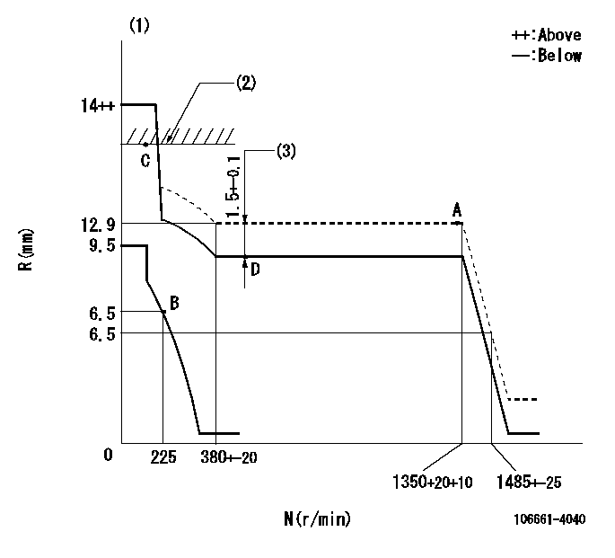
N:Pump speed
R:Rack position (mm)
(1)Target notch: K
(2)RACK LIMIT: RAL
(3)Boost compensator stroke
----------
K=12 RAL=13.1+0.2mm
----------
----------
K=12 RAL=13.1+0.2mm
----------
Speed control lever angle
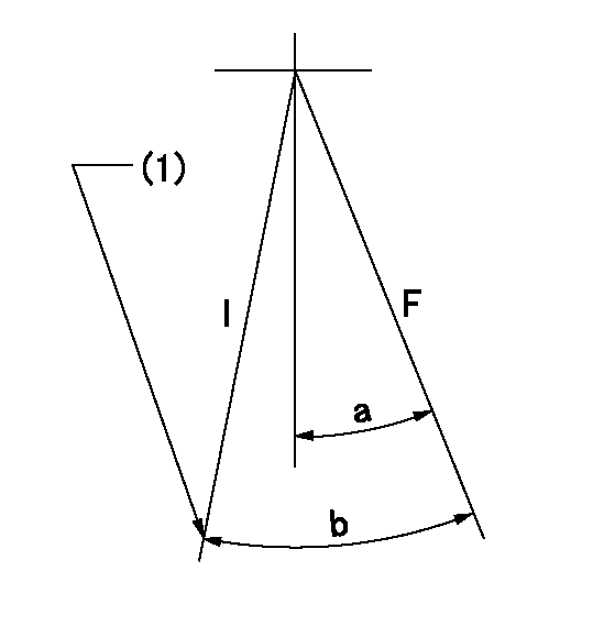
F:Full speed
I:Idle
(1)Stopper bolt setting
----------
----------
a=12deg+-5deg b=30deg+-5deg
----------
----------
a=12deg+-5deg b=30deg+-5deg
Stop lever angle

N:Pump normal
S:Stop the pump.
(1)Pump speed aa and rack position bb (to be sealed at delivery)
----------
aa=0r/min bb=1-0.2mm
----------
a=25deg+-5deg b=70deg+-5deg
----------
aa=0r/min bb=1-0.2mm
----------
a=25deg+-5deg b=70deg+-5deg
Timing setting

(1)Pump vertical direction
(2)Coupling's key groove position for the No. 6 cylinder's beginning of injection
(3)-
(4)-
----------
----------
a=(120deg)
----------
----------
a=(120deg)
Information:
Parts Required For 4C-8180 Timing Tool Group
Refer to Chart A for item identification.Assemble and Set the 4C-8180 Timing Tool Group
1. Obtain a 108-2104 Plunger and Barrel Assembly. This part can be new or used. If the part is used, make sure it is in good working condition. The plunger should move freely in the barrel.
4C-8181 Timing Tool Assembly
(9) 8J-3819 Spring. (10) 1N-3257 Retainer Ring. (11) Plunger and barrel from 108-2104 Plunger and Barrel Assembly. (12) 4C-8178 Indicator Mount Bonnet. (14) 4C-8179 Bonnet Nut. (16) 2W-3429 Gear Segment (part of 108-2104). (17) 8N-0669 Bolt (part of 108-2104). (18) 4P-8704 Spring (part of 108-2104). (19) 9Y-2088 Washer.2. Make a 4C-8181 Timing Tool Assembly out of the 108-2104 Plunger and Barrel Assembly. The 4C-8181 Timing Tool Assembly is not a serviceable part. a. Remove and discard 8N-0669 Bolt (17), 2W-3429 Gear Segment (16), and 4P-8704 Spring (18) from the 108-2104 Plunger and Barrel Assembly.b. Assemble 8J-3819 Spring (9) and 9Y-2088 Washer (19) onto plunger. The 9Y-2088 Washer is part of the 108-2104 Plunger and Barrel Assembly.c. Install the 4C-8178 Indicator Mount Bonnet (12) onto the barrel using a 1N-3257 Retainer Ring (10).d. Slip 4C-8179 Bonnet Nut (14) over indicator mount bonnet (12).e. This tool is now a 4C-8181 Timing Tool Assembly (11).3. Assemble knurled gauge collar (3) onto gauge (5) by threading them together. Hand tighten the two parts. Make sure the gauging surfaces are clean and free of all debris, nicks, etc.4. Install 4C-8181 Timing Tool Assembly (11) into gauge collar (3).5. Thread bonnet nut (14) into gauge collar (3) and hand tighten with 9U-5120 Spanner Wrench (13). This will secure timing tool assembly (11) into gauge collar (3).6. Spring (9) on the timing tool assembly should make the end of the plunger extend approximately 30 mm (1.2 in) past the end of gauge (5).7. Push on the end of the plunger and make sure it travels freely (under spring force) in and out of the gauge block bore. If there is binding, disassemble and correct the problem.8. Install either a 5P-4814 Collet (6) or 4C-2982 Collet Assembly (7) into indicator mount bonnet (12).9. Install an indicator with a 5P-7262 Contact Point into collet (6 or 7). Use either a 6V-6106 Dial Indicator or an 8T-1002 Probe connected to an 8T-1001 Electronic Position Indicator.
Do not over tighten collet (6 or 7) holding the indicator. Over-tightening can result in damage to the indicator or the electronic position indicator probe.
10. Tighten collet (6 or 7) just enough to make sure the indicator or electronic position indicator probe will not move in collet.11. Zero the indicator by following this procedure. a. Place the 4C-8183 Gauge Plate (8) onto a flat surface.b. Carefully hold the entire 4C-8180 Timing Tool Group and place it on the gauge plate, with the end of the plunger contacting the plate.c. Push down on the entire assembly, compressing the spring, until the bottom of gauge (5) is in complete contact with gauge plate (8).
Zero The Timing Tool Assembly With