Information injection-pump assembly
BOSCH
9 400 616 602
9400616602
ZEXEL
106661-4000
1066614000
DAIHATSU
M121610010A
m121610010a
Rating:
Service parts 106661-4000 INJECTION-PUMP ASSEMBLY:
1.
_
7.
COUPLING PLATE
8.
_
9.
_
11.
Nozzle and Holder
M126410160ZZ
12.
Open Pre:MPa(Kqf/cm2)
14.7{150}
15.
NOZZLE SET
Include in #1:
106661-4000
as INJECTION-PUMP ASSEMBLY
Cross reference number
BOSCH
9 400 616 602
9400616602
ZEXEL
106661-4000
1066614000
DAIHATSU
M121610010A
m121610010a
Zexel num
Bosch num
Firm num
Name
106661-4000
9 400 616 602
M121610010A DAIHATSU
INJECTION-PUMP ASSEMBLY
M2 K
M2 K
Calibration Data:
Adjustment conditions
Test oil
1404 Test oil ISO4113 or {SAEJ967d}
1404 Test oil ISO4113 or {SAEJ967d}
Test oil temperature
degC
40
40
45
Nozzle
105780-0030
Nozzle holder
105780-2090
Bosch type code
EFEP215
Opening pressure
MPa
17.2
Opening pressure
kgf/cm2
175
Injection pipe
Outer diameter - inner diameter - length (mm) mm 8-3-600
Outer diameter - inner diameter - length (mm) mm 8-3-600
Overflow valve
131424-1520
Overflow valve opening pressure
kPa
157
123
191
Overflow valve opening pressure
kgf/cm2
1.6
1.25
1.95
Tester oil delivery pressure
kPa
157
157
157
Tester oil delivery pressure
kgf/cm2
1.6
1.6
1.6
Direction of rotation (viewed from drive side)
Right R
Right R
Injection timing adjustment
Direction of rotation (viewed from drive side)
Right R
Right R
Injection order
1-4-2-6-
3-5
Pre-stroke
mm
2.05
2
2.1
Beginning of injection position
Governor side NO.1
Governor side NO.1
Difference between angles 1
Cal 1-4 deg. 60 59.5 60.5
Cal 1-4 deg. 60 59.5 60.5
Difference between angles 2
Cyl.1-2 deg. 120 119.5 120.5
Cyl.1-2 deg. 120 119.5 120.5
Difference between angles 3
Cal 1-6 deg. 180 179.5 180.5
Cal 1-6 deg. 180 179.5 180.5
Difference between angles 4
Cal 1-3 deg. 240 239.5 240.5
Cal 1-3 deg. 240 239.5 240.5
Difference between angles 5
Cal 1-5 deg. 300 299.5 300.5
Cal 1-5 deg. 300 299.5 300.5
Injection quantity adjustment
Adjusting point
A
Rack position
R(10)
Pump speed
r/min
930
930
930
Average injection quantity
mm3/st.
157
152.2
161.8
Max. variation between cylinders
%
0
-3
3
Basic
*
Fixing the rack
*
Injection quantity adjustment_02
Adjusting point
B
Rack position
5.5+-0.5
Pump speed
r/min
300
300
300
Average injection quantity
mm3/st.
25
22.5
27.5
Max. variation between cylinders
%
0
-10
10
Fixing the rack
*
Timer adjustment
Pump speed
r/min
750+-50
Advance angle
deg.
0
0
0
Remarks
Start
Start
Timer adjustment_02
Pump speed
r/min
900
Advance angle
deg.
2
1.5
2.5
Timer adjustment_03
Pump speed
r/min
1000
Advance angle
deg.
4
3.5
4.5
Remarks
Finish
Finish
Test data Ex:
Governor adjustment
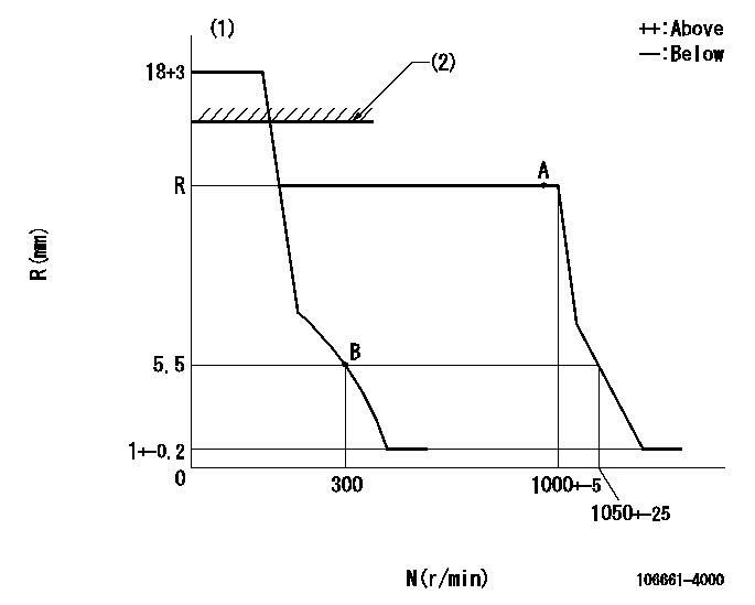
N:Pump speed
R:Rack position (mm)
(1)Target notch: K
(2)RACK LIMIT: RAL
----------
K=10 RAL=14+-0.5mm
----------
----------
K=10 RAL=14+-0.5mm
----------
Speed control lever angle
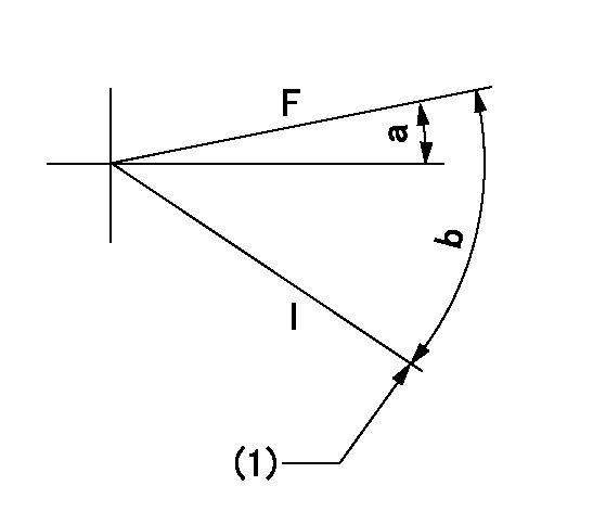
F:Full speed
I:Idle
(1)Stopper bolt setting
----------
----------
a=4deg+-5deg b=27deg+-5deg
----------
----------
a=4deg+-5deg b=27deg+-5deg
Stop lever angle
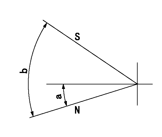
N:Pump normal
S:Stop the pump.
----------
----------
a=(11deg) b=(53deg)
----------
----------
a=(11deg) b=(53deg)
Information:
Outside Leaks
Leaks in Hoses or Connections ... Check all hoses and connections for visual signs of leakage. If no leaks are seen, look for damage to hoses or loose clamps.Leaks in the Radiator and/or Expansion Tank ... Put pressure to the radiator and/or expansion tank with a cooling system pressurizing pump and check for leaks.Leaks in the Heater ... Put pressure to the cooling system with a cooling system pressurizing pump and check the heater for leaks.Leaks in the Water Pump ... Check the water pump for leaks before starting the engine, then start the engine and look for leaks. If there are leaks at the water pump, install a new water pump.Cylinder Head Gasket Leakage ... Look for leaks along the surface of the cylinder head gasket. If you see leaks, install a new head gasket.Coolant Leaks At The Overflow Tube
Defective Pressure Cap ... Check the sealing surfaces of the pressure cap and the radiator to be sure the cap is sealing correctly. Check the opening pressure and sealing ability of the pressure cap with a cooling system pressurizing pump.Engine Runs Too Hot ... If coolant temperature is too high, pressure will be high enough to lift the cap off of the sealing surface in the radiator and cause coolant loss through the overflow tube. See "Above Normal Heating" in COOLING SYSTEM chart.Expansion Tank Too Small or Installed Wrong ... The expansion tank can be either a part of the radiator or it can be installed separately from the radiator. The expansion tank must be large enough to hold the expansion of the coolant as it gets warm or has sudden changes in pressure. Make sure the expansion tank is installed correctly and is according to the recommendations of the truck manufacturer.Cylinder Head Gasket Leakage, or Crack(s) in Cylinder Head or Cylinder Block ... Remove the radiator cap and with the engine running look for air bubbles in the coolant. Bubbles in the coolant are a sign of probable leakage at the head gasket. With the engine not running, check each cylinder with the cylinder leakage tester. If you see air bubbles in the coolant during this test, there is a leak of combustion gas into the cooling system. Remove the cylinder heads from the engine. Check cylinder heads, cylinder walls and head gasket surface of cylinder block for cracks. When installing heads, use new head gaskets. *Inside Leakage
Cylinder Head Gasket Leakage ... If the cylinder head gasket leaks between a water passage and an opening into the crankcase, coolant will get into the crankcase.Crack(s) in Cylinder Head ... Crack(s) in the upper surface of the cylinder head or an area between a water passage and an opening into the crankcase can allow coolant to get into the crankcase.Crack(s) in Cylinder Block ... Crack(s) in the cylinder block between a water passage and the crankcase will let coolant get into the crankcase.*Authorized dealers are equipped with the necessary tools and personnel familiar with disassembly and assembly procedures
Have questions with 106661-4000?
Group cross 106661-4000 ZEXEL
Daihatsu
106661-4000
9 400 616 602
M121610010A
INJECTION-PUMP ASSEMBLY
M2
M2