Information injection-pump assembly
BOSCH
9 400 616 593
9400616593
ZEXEL
106661-2101
1066612101
MITSUBISHI
ME056851
me056851
Rating:
Service parts 106661-2101 INJECTION-PUMP ASSEMBLY:
1.
_
7.
COUPLING PLATE
8.
_
9.
_
11.
Nozzle and Holder
ME056804
12.
Open Pre:MPa(Kqf/cm2)
17.7{180}/24.5{250}
15.
NOZZLE SET
Include in #1:
106661-2101
as INJECTION-PUMP ASSEMBLY
Cross reference number
BOSCH
9 400 616 593
9400616593
ZEXEL
106661-2101
1066612101
MITSUBISHI
ME056851
me056851
Zexel num
Bosch num
Firm num
Name
106661-2101
9 400 616 593
ME056851 MITSUBISHI
INJECTION-PUMP ASSEMBLY
6D22T2 K 14CA INJECTION PUMP ASSY PE6P,6PD PE
6D22T2 K 14CA INJECTION PUMP ASSY PE6P,6PD PE
Calibration Data:
Adjustment conditions
Test oil
1404 Test oil ISO4113 or {SAEJ967d}
1404 Test oil ISO4113 or {SAEJ967d}
Test oil temperature
degC
40
40
45
Nozzle and nozzle holder
105780-8140
Bosch type code
EF8511/9A
Nozzle
105780-0000
Bosch type code
DN12SD12T
Nozzle holder
105780-2080
Bosch type code
EF8511/9
Opening pressure
MPa
17.2
Opening pressure
kgf/cm2
175
Injection pipe
Inside diameter - outside diameter - length (mm) mm 8-3-600
Inside diameter - outside diameter - length (mm) mm 8-3-600
Overflow valve
131424-6920
Overflow valve opening pressure
kPa
191
157
225
Overflow valve opening pressure
kgf/cm2
1.95
1.6
2.3
Tester oil delivery pressure
kPa
157
157
157
Tester oil delivery pressure
kgf/cm2
1.6
1.6
1.6
Direction of rotation (viewed from drive side)
Right R
Right R
Injection timing adjustment
Direction of rotation (viewed from drive side)
Right R
Right R
Injection order
1-5-3-6-
2-4
Pre-stroke
mm
4.8
4.75
4.85
Beginning of injection position
Governor side NO.1
Governor side NO.1
Difference between angles 1
Cal 1-5 deg. 60 59.5 60.5
Cal 1-5 deg. 60 59.5 60.5
Difference between angles 2
Cal 1-3 deg. 120 119.5 120.5
Cal 1-3 deg. 120 119.5 120.5
Difference between angles 3
Cal 1-6 deg. 180 179.5 180.5
Cal 1-6 deg. 180 179.5 180.5
Difference between angles 4
Cyl.1-2 deg. 240 239.5 240.5
Cyl.1-2 deg. 240 239.5 240.5
Difference between angles 5
Cal 1-4 deg. 300 299.5 300.5
Cal 1-4 deg. 300 299.5 300.5
Injection quantity adjustment
Adjusting point
-
Rack position
10.6
Pump speed
r/min
700
700
700
Each cylinder's injection qty
mm3/st.
149
145.3
152.7
Basic
*
Fixing the rack
*
Standard for adjustment of the maximum variation between cylinders
*
Injection quantity adjustment_02
Adjusting point
C
Rack position
6+-0.5
Pump speed
r/min
225
225
225
Each cylinder's injection qty
mm3/st.
11.5
9.8
13.2
Fixing the rack
*
Standard for adjustment of the maximum variation between cylinders
*
Injection quantity adjustment_03
Adjusting point
A
Rack position
R1(10.6)
Pump speed
r/min
700
700
700
Average injection quantity
mm3/st.
149
148
150
Basic
*
Fixing the lever
*
Boost pressure
kPa
29.3
29.3
Boost pressure
mmHg
220
220
Injection quantity adjustment_04
Adjusting point
B
Rack position
R1-0.35
Pump speed
r/min
1100
1100
1100
Average injection quantity
mm3/st.
147.5
145.5
149.5
Fixing the lever
*
Boost pressure
kPa
29.3
29.3
Boost pressure
mmHg
220
220
Injection quantity adjustment_05
Adjusting point
D
Rack position
R1-1.7
Pump speed
r/min
700
700
700
Average injection quantity
mm3/st.
117
114
120
Fixing the lever
*
Boost pressure
kPa
0
0
0
Boost pressure
mmHg
0
0
0
Injection quantity adjustment_06
Adjusting point
F
Rack position
-
Pump speed
r/min
100
100
100
Average injection quantity
mm3/st.
131
91
171
Fixing the lever
*
Boost pressure
kPa
0
0
0
Boost pressure
mmHg
0
0
0
Boost compensator adjustment
Pump speed
r/min
700
700
700
Rack position
R2(R1-1.
7)
Boost pressure
kPa
6
6
6
Boost pressure
mmHg
45
45
45
Boost compensator adjustment_02
Pump speed
r/min
700
700
700
Rack position
R1-0.8
Boost pressure
kPa
10
8.7
11.3
Boost pressure
mmHg
75
65
85
Boost compensator adjustment_03
Pump speed
r/min
700
700
700
Rack position
R1(10.6)
Boost pressure
kPa
16
16
16
Boost pressure
mmHg
120
120
120
Test data Ex:
Governor adjustment
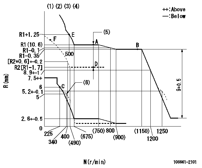
N:Pump speed
R:Rack position (mm)
(1)Lever ratio: RT
(2)Target shim dimension: TH
(3)Tolerance for racks not indicated: +-0.05mm.
(4)Boost compensator cancel stroke: BSL
(5)Boost compensator stroke: BCL
(6)Damper spring setting
----------
RT=1 TH=2.9mm BSL=1.8mm BCL=1.7+-0.1mm
----------
----------
RT=1 TH=2.9mm BSL=1.8mm BCL=1.7+-0.1mm
----------
Timer adjustment
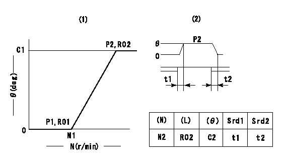
(1)Adjusting range
(2)Step response time
(N): Speed of the pump
(L): Load
(theta) Advance angle
(Srd1) Step response time 1
(Srd2) Step response time 2
1. Adjusting conditions for the variable timer
(1)Adjust the clearance between the pickup and the protrusion to L.
----------
L=1-0.2mm N2=800r/min C2=(8.8)deg t1=2.5--sec. t2=2.5--sec.
----------
N1=750++r/min P1=0kPa(0kgf/cm2) P2=392kPa(4kgf/cm2) C1=8.8+-0.3deg R01=0/4load R02=4/4load
----------
L=1-0.2mm N2=800r/min C2=(8.8)deg t1=2.5--sec. t2=2.5--sec.
----------
N1=750++r/min P1=0kPa(0kgf/cm2) P2=392kPa(4kgf/cm2) C1=8.8+-0.3deg R01=0/4load R02=4/4load
Speed control lever angle
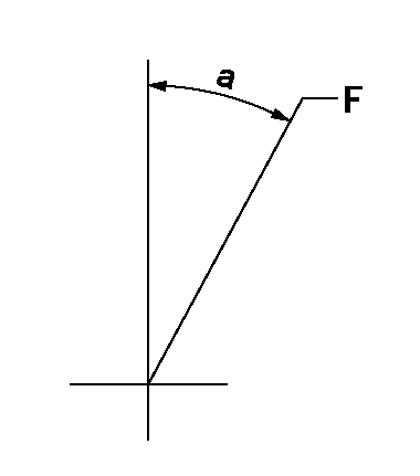
F:Full speed
----------
----------
a=14.5deg+-5deg
----------
----------
a=14.5deg+-5deg
0000000901
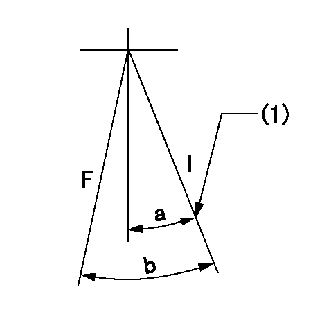
F:Full load
I:Idle
(1)Stopper bolt setting
----------
----------
a=28deg+-5deg b=29.5deg+-3deg
----------
----------
a=28deg+-5deg b=29.5deg+-3deg
Stop lever angle
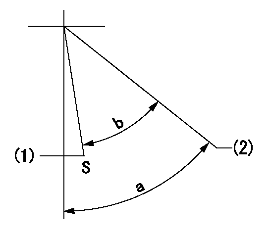
S:Stop the pump.
(1)Rack position = aa, stopper bolt setting
(2)Free (at delivery)
----------
aa=3.8-0.5mm
----------
a=38deg+-5deg b=37.5deg+7deg-5deg
----------
aa=3.8-0.5mm
----------
a=38deg+-5deg b=37.5deg+7deg-5deg
0000001501 MICRO SWITCH
Adjustment of the micro-switch
Adjust the bolt to obtain the following lever position when the micro-switch is ON.
(1)Speed N1
(2)Rack position Ra
----------
N1=325r/min Ra=5.7+-0.1mm
----------
----------
N1=325r/min Ra=5.7+-0.1mm
----------
0000001601 RACK SENSOR

V1:Supply voltage
V2f:Full side output voltage
V2i:Idle side output voltage
(A) Black
(B) Yellow
(C) Red
(D) Trimmer
(E): Shaft
(F) Nut
(G) Load lever
1. Load sensor adjustment
(1)Connect as shown in the above diagram and apply supply voltage V1.
(2)Hold the load lever (G) against the full side.
(3)Turn the shaft so that the voltage between (A) and (B) is V2.
(4)Hold the load lever (G) against the idle side.
(5)Adjust (D) so that the voltage between (A) and (B) is V2i.
(6)Repeat the above adjustments.
(7)Tighten the nut (F) at the point satisfying the standards.
(8)Hold the load lever against the full side stopper and the idle side stopper.
(9)At this time, confirm that the full side output voltage is V2f and the idle side output voltage is V2i.
----------
V1= 5+-0.02V V2f=0.15+0.03V V2i=2.35-0.03V
----------
----------
V1= 5+-0.02V V2f=0.15+0.03V V2i=2.35-0.03V
----------
0000001701 SPEED SENSOR
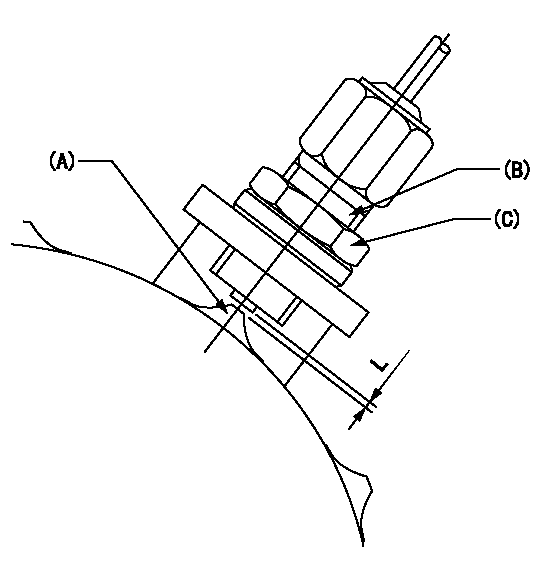
(A) Flyweight projection
(B) Pickup sensor
(c) Lock nut
Speed sensor installation
(1)Install the speed sensor so that the clearance between the sensor and the flyweight projection is L.
(This gap is the gap when the pickup sensor is returned 1 turn from where it contacts the flyweight tooth.)
----------
L=0.8~1mm
----------
----------
L=0.8~1mm
----------
Timing setting

(1)Pump vertical direction
(2)Coupling's key groove position at No 1 cylinder's beginning of injection
(3)B.T.D.C.: aa
(4)-
----------
aa=9deg
----------
a=(7deg)
----------
aa=9deg
----------
a=(7deg)
Information:
To receive satisfactory engine performance with maximum fuel economy and service life, the following engine operation instructions must be applied. In addition, it is necessary to also apply the recommendations of the vehicle manufacturer as well as the every day rules of good driving.After the engine starts, reduce engine RPM to low idle with no load. When normal oil pressure is reached, operate the engine at low load for 5 minutes before applying full load.Stop Engine At Once If Any Part Fails
Almost all failures give a warning to the operator before the part completely fails. If the operator is alert and heeds the warnings, further damage may not happen. A few of the warning signs are: abnormal gauge readings, abnormal fluid levels, fluid leaks, unusual engine noises and excessive smoke. Do not operate an engine if any sign of part failure is present, only a few seconds can ruin an entire engine.Start vehicle in motion by utilizing the lowest gear speed in the transmission that will enable the engine to easily start the load without slipping the clutch. Accelerate smoothly and evenly until the engine speed reaches approximately 100% of rated RPM. Rapid depression of accelerator will result in undesirable heavy exhaust smoke and high fuel consumption with no increase in vehicle performance. Upshift to the next higher gear speed. If properly done, the engine speed will be above approximately 80% of rated RPM when the load is applied. For best performance do not skip gears. Engine speed should not be permitted to drop appreciably below 80% of rated RPM, to avoid a lugging condition.Caterpillar engines have good lugging characteristics; however, operating in a lug condition for extended periods of time should be avoided as it causes exhaust temperatures to rise and also results in high fuel consumption. A lug condition exists when an increase in engine speed cannot be achieved with an increase in accelerator pedal position, or when engine speed decreases with the accelerator pedal in its maximum position. A lug condition can exist at any engine speed below full load speed. Continue to make successive upshifts through each gear speed in the transmission until cruising speed is reached. In each gear speed, accelerate smoothly to an engine speed of approximately 100% of rated RPM before upshifting to the next gear. For highway cruising, maintain the engine speed between approximately 80% and 100% of rated RPM. Operating in this range will give maximum fuel economy.When going up a grade and the engine speed drops to below approximately 80% of rated RPM, downshift successively until a gear speed is reached that will enable the engine to pull the load without operating in a lug condition. When pulling a long grade, such as encountered in mountain driving, make additional downshifts of one or two gears immediately prior to reaching the summit. This will allow the engine to cool more slowly than if the load on the engine is suddenly changed from a full load condition going uphill to
Almost all failures give a warning to the operator before the part completely fails. If the operator is alert and heeds the warnings, further damage may not happen. A few of the warning signs are: abnormal gauge readings, abnormal fluid levels, fluid leaks, unusual engine noises and excessive smoke. Do not operate an engine if any sign of part failure is present, only a few seconds can ruin an entire engine.Start vehicle in motion by utilizing the lowest gear speed in the transmission that will enable the engine to easily start the load without slipping the clutch. Accelerate smoothly and evenly until the engine speed reaches approximately 100% of rated RPM. Rapid depression of accelerator will result in undesirable heavy exhaust smoke and high fuel consumption with no increase in vehicle performance. Upshift to the next higher gear speed. If properly done, the engine speed will be above approximately 80% of rated RPM when the load is applied. For best performance do not skip gears. Engine speed should not be permitted to drop appreciably below 80% of rated RPM, to avoid a lugging condition.Caterpillar engines have good lugging characteristics; however, operating in a lug condition for extended periods of time should be avoided as it causes exhaust temperatures to rise and also results in high fuel consumption. A lug condition exists when an increase in engine speed cannot be achieved with an increase in accelerator pedal position, or when engine speed decreases with the accelerator pedal in its maximum position. A lug condition can exist at any engine speed below full load speed. Continue to make successive upshifts through each gear speed in the transmission until cruising speed is reached. In each gear speed, accelerate smoothly to an engine speed of approximately 100% of rated RPM before upshifting to the next gear. For highway cruising, maintain the engine speed between approximately 80% and 100% of rated RPM. Operating in this range will give maximum fuel economy.When going up a grade and the engine speed drops to below approximately 80% of rated RPM, downshift successively until a gear speed is reached that will enable the engine to pull the load without operating in a lug condition. When pulling a long grade, such as encountered in mountain driving, make additional downshifts of one or two gears immediately prior to reaching the summit. This will allow the engine to cool more slowly than if the load on the engine is suddenly changed from a full load condition going uphill to
Have questions with 106661-2101?
Group cross 106661-2101 ZEXEL
Mitsubishi
106661-2101
9 400 616 593
ME056851
INJECTION-PUMP ASSEMBLY
6D22T2
6D22T2
