Information injection-pump assembly
BOSCH
9 400 616 590
9400616590
ZEXEL
106661-2051
1066612051
MITSUBISHI
ME056799
me056799

Rating:
Service parts 106661-2051 INJECTION-PUMP ASSEMBLY:
1.
_
7.
COUPLING PLATE
8.
_
9.
_
11.
Nozzle and Holder
ME056804
12.
Open Pre:MPa(Kqf/cm2)
17.7{180}/24.5{250}

15.
NOZZLE SET
Include in #1:
106661-2051
as INJECTION-PUMP ASSEMBLY
Cross reference number
BOSCH
9 400 616 590
9400616590
ZEXEL
106661-2051
1066612051
MITSUBISHI
ME056799
me056799
Zexel num
Bosch num
Firm num
Name
9 400 616 590
ME056799 MITSUBISHI
INJECTION-PUMP ASSEMBLY
6D22T6 K 14CA INJECTION PUMP ASSY PE6P,6PD PE
6D22T6 K 14CA INJECTION PUMP ASSY PE6P,6PD PE
Calibration Data:
Adjustment conditions
Test oil
1404 Test oil ISO4113 or {SAEJ967d}
1404 Test oil ISO4113 or {SAEJ967d}
Test oil temperature
degC
40
40
45
Nozzle and nozzle holder
105780-8140
Bosch type code
EF8511/9A
Nozzle
105780-0000
Bosch type code
DN12SD12T
Nozzle holder
105780-2080
Bosch type code
EF8511/9
Opening pressure
MPa
17.2
Opening pressure
kgf/cm2
175
Injection pipe
Outer diameter - inner diameter - length (mm) mm 8-3-600
Outer diameter - inner diameter - length (mm) mm 8-3-600
Overflow valve
131424-6920
Overflow valve opening pressure
kPa
191
157
225
Overflow valve opening pressure
kgf/cm2
1.95
1.6
2.3
Tester oil delivery pressure
kPa
157
157
157
Tester oil delivery pressure
kgf/cm2
1.6
1.6
1.6
Direction of rotation (viewed from drive side)
Right R
Right R
Injection timing adjustment
Direction of rotation (viewed from drive side)
Right R
Right R
Injection order
1-5-3-6-
2-4
Pre-stroke
mm
4.8
4.75
4.85
Beginning of injection position
Governor side NO.1
Governor side NO.1
Difference between angles 1
Cal 1-5 deg. 60 59.5 60.5
Cal 1-5 deg. 60 59.5 60.5
Difference between angles 2
Cal 1-3 deg. 120 119.5 120.5
Cal 1-3 deg. 120 119.5 120.5
Difference between angles 3
Cal 1-6 deg. 180 179.5 180.5
Cal 1-6 deg. 180 179.5 180.5
Difference between angles 4
Cyl.1-2 deg. 240 239.5 240.5
Cyl.1-2 deg. 240 239.5 240.5
Difference between angles 5
Cal 1-4 deg. 300 299.5 300.5
Cal 1-4 deg. 300 299.5 300.5
Injection quantity adjustment
Adjusting point
-
Rack position
10.2
Pump speed
r/min
650
650
650
Each cylinder's injection qty
mm3/st.
138.5
135.1
141.9
Basic
*
Fixing the rack
*
Standard for adjustment of the maximum variation between cylinders
*
Injection quantity adjustment_02
Adjusting point
C
Rack position
6.5+-0.5
Pump speed
r/min
225
225
225
Each cylinder's injection qty
mm3/st.
17.5
14.9
20.1
Fixing the rack
*
Standard for adjustment of the maximum variation between cylinders
*
Injection quantity adjustment_03
Adjusting point
A
Rack position
R1(10.2)
Pump speed
r/min
650
650
650
Average injection quantity
mm3/st.
138.5
137.5
139.5
Basic
*
Fixing the lever
*
Boost pressure
kPa
27.3
27.3
Boost pressure
mmHg
205
205
Injection quantity adjustment_04
Adjusting point
D
Rack position
8.6
Pump speed
r/min
700
700
700
Average injection quantity
mm3/st.
101.5
98.5
104.5
Fixing the lever
*
Boost pressure
kPa
0
0
0
Boost pressure
mmHg
0
0
0
Injection quantity adjustment_05
Adjusting point
E
Rack position
-
Pump speed
r/min
100
100
100
Average injection quantity
mm3/st.
135
115
155
Fixing the lever
*
Boost pressure
kPa
0
0
0
Boost pressure
mmHg
0
0
0
Boost compensator adjustment
Pump speed
r/min
600
600
600
Rack position
8.6
Boost pressure
kPa
5.3
5.3
5.3
Boost pressure
mmHg
40
40
40
Boost compensator adjustment_02
Pump speed
r/min
600
600
600
Rack position
R1(10.2)
Boost pressure
kPa
14
14
14
Boost pressure
mmHg
105
105
105
Timer adjustment
Pump speed
r/min
950--
Advance angle
deg.
0
0
0
Load
4/4
Remarks
Start
Start
Timer adjustment_02
Pump speed
r/min
900
Advance angle
deg.
0.5
Load
3/4
Timer adjustment_03
Pump speed
r/min
1100
Advance angle
deg.
4
3.5
4.5
Load
4/4
Remarks
Finish
Finish
Test data Ex:
Governor adjustment
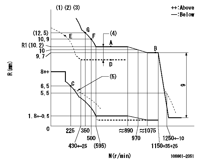
N:Pump speed
R:Rack position (mm)
(1)Lever ratio: RT
(2)Target shim dimension: TH
(3)Boost compensator cancel stroke: BSL
(4)Boost compensator stroke: BCL
(5)Damper spring setting: DL
----------
RT=1 TH=2.1mm BSL=1.6mm BCL=1.6+-0.1mm DL=6.2-0.2mm
----------
----------
RT=1 TH=2.1mm BSL=1.6mm BCL=1.6+-0.1mm DL=6.2-0.2mm
----------
Speed control lever angle

F:Full speed
----------
----------
a=15.5deg+-5deg
----------
----------
a=15.5deg+-5deg
0000000901
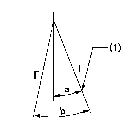
F:Full load
I:Idle
(1)Stopper bolt setting
----------
----------
a=28deg+-5deg b=31deg+-3deg
----------
----------
a=28deg+-5deg b=31deg+-3deg
Stop lever angle
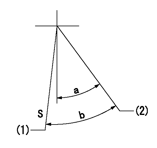
S:Stop the pump.
(1)Rack position = aa
(2)Free (at shipping)
----------
aa=3.4-0.5mm
----------
a=35.5deg+-5deg b=38.5deg+7deg-5deg
----------
aa=3.4-0.5mm
----------
a=35.5deg+-5deg b=38.5deg+7deg-5deg
0000001501 MICRO SWITCH
Adjustment of the micro-switch
Adjust the bolt to obtain the following lever position when the micro-switch is ON.
(1)Speed N1
(2)Rack position Ra
----------
N1=325+-5r/min Ra=6.2mm
----------
----------
N1=325+-5r/min Ra=6.2mm
----------
Timing setting

(1)Pump vertical direction
(2)Coupling's key groove position at No 1 cylinder's beginning of injection
(3)B.T.D.C.: aa
(4)-
----------
aa=13deg
----------
a=(7deg)
----------
aa=13deg
----------
a=(7deg)
Information:
This engine has a pressurized cooling system. Coolant is circulated by a belt driven, centrifugal type water pump. A water temperature regulator, located at the left front of the cylinder head, restricts coolant flow through the radiator until the coolant reaches operating temperature.The water pump has two outlets. One outlet directs coolant through a passage in the water temperature regulator housing to the aftercooler, to lower the temperature of inlet air in the inlet manifold. The other water outlet directs coolant through a water manifold in the side of the cylinder block, to cool engine lubricating oil. Coolant flows from the water manifold around the cylinder liners, into the cylinder head and around the precombustion chambers. Both streams of water join at the water temperature regulator. The water cooled air compressor receives coolant through a tube that is connected to the water manifold in the side of the cylinder block. Coolant returns through a tube from the air compressor head to the diesel engine cylinder head.Until the coolant reaches the temperature required to open the temperature regulator, coolant bypasses the radiator and flows directly back to the water pump.When the coolant reaches the temperature required to open the temperature regulator, coolant is then directed through the radiator.A pressure relief cap assembly is used to control the pressure in the cooling system, and prevents loss of coolant through the radiator overflow tube.Pressurizing the cooling system serves two purposes. First, it permits safe operation at coolant temperatures higher than the normal boiling point, providing a margin of cooling for intermittent peak loads. Secondly, it prevents cavitation in the water pump, and reduces the possibility of air or steam pockets forming in the coolant passages. Proper operation of the pressure relief cap assembly is essential. A pressure relief cap allows pressure (and some water, if the cooling system is too full) to escape when the pressure in the cooling system exceeds the capacity of the pressure cap. Loss of pressure will cause steam to form when coolant temperature is above the normal boiling point.Water Pump
The centrifugal-type water pump has two seals, one prevents leakage of water and the other prevents leakage of lubricant.An opening in the bottom of the pump housing, allows any leakage at the water seal or the rear bearing oil seal to escape.Fan
The fan is driven by three V-belts, from a pulley on the crankshaft. Belt tension is adjusted by moving the bracket assembly which includes the fan mounting and pulley.Water Temperature Regulator
The water temperature regulator restricts the flow of coolant through the radiator, until the coolant reaches operating temperature; approximately 165°F (74°C.) The regulator is fully open at approximately 180°F (82°C.)The shunt cooling system is used in many truck installations. The shunt cooling system provides continuous circulation which helps prevent aeration and pump cavitation by maintaining a positive head of water at the pump inlet at all times. It differs from the conventional cooling system in that the radiator top tank is divided into two compartments (upper