Information injection-pump assembly
BOSCH
9 400 616 587
9400616587
ZEXEL
106661-0936
1066610936
NISSAN-DIESEL
1670096608
1670096608

Rating:
Service parts 106661-0936 INJECTION-PUMP ASSEMBLY:
1.
_
7.
COUPLING PLATE
8.
_
9.
_
10.
NOZZLE AND HOLDER ASSY
11.
Nozzle and Holder
12.
Open Pre:MPa(Kqf/cm2)
13.
NOZZLE-HOLDER
14.
NOZZLE
15.
NOZZLE SET
Include in #1:
106661-0936
as INJECTION-PUMP ASSEMBLY
Cross reference number
BOSCH
9 400 616 587
9400616587
ZEXEL
106661-0936
1066610936
NISSAN-DIESEL
1670096608
1670096608
Zexel num
Bosch num
Firm num
Name
106661-0936
9 400 616 587
1670096608 NISSAN-DIESEL
INJECTION-PUMP ASSEMBLY
PE6T * K
PE6T * K
Calibration Data:
Adjustment conditions
Test oil
1404 Test oil ISO4113 or {SAEJ967d}
1404 Test oil ISO4113 or {SAEJ967d}
Test oil temperature
degC
40
40
45
Nozzle and nozzle holder
105780-8140
Bosch type code
EF8511/9A
Nozzle
105780-0000
Bosch type code
DN12SD12T
Nozzle holder
105780-2080
Bosch type code
EF8511/9
Opening pressure
MPa
17.2
Opening pressure
kgf/cm2
175
Injection pipe
Outer diameter - inner diameter - length (mm) mm 8-3-600
Outer diameter - inner diameter - length (mm) mm 8-3-600
Overflow valve opening pressure
kPa
157
123
191
Overflow valve opening pressure
kgf/cm2
1.6
1.25
1.95
Tester oil delivery pressure
kPa
157
157
157
Tester oil delivery pressure
kgf/cm2
1.6
1.6
1.6
Direction of rotation (viewed from drive side)
Right R
Right R
Injection timing adjustment
Direction of rotation (viewed from drive side)
Right R
Right R
Injection order
1-4-2-6-
3-5
Pre-stroke
mm
3.2
3.15
3.25
Beginning of injection position
Drive side NO.1
Drive side NO.1
Difference between angles 1
Cal 1-4 deg. 60 59.5 60.5
Cal 1-4 deg. 60 59.5 60.5
Difference between angles 2
Cyl.1-2 deg. 120 119.5 120.5
Cyl.1-2 deg. 120 119.5 120.5
Difference between angles 3
Cal 1-6 deg. 180 179.5 180.5
Cal 1-6 deg. 180 179.5 180.5
Difference between angles 4
Cal 1-3 deg. 240 239.5 240.5
Cal 1-3 deg. 240 239.5 240.5
Difference between angles 5
Cal 1-5 deg. 300 299.5 300.5
Cal 1-5 deg. 300 299.5 300.5
Injection quantity adjustment
Adjusting point
A
Rack position
12.3
Pump speed
r/min
650
650
650
Average injection quantity
mm3/st.
164.2
162.2
166.2
Max. variation between cylinders
%
0
-4
4
Basic
*
Fixing the lever
*
Boost pressure
kPa
32
32
Boost pressure
mmHg
240
240
Injection quantity adjustment_02
Adjusting point
B
Rack position
6+-0.5
Pump speed
r/min
225
225
225
Average injection quantity
mm3/st.
9.1
8.1
10.1
Max. variation between cylinders
%
0
-10
10
Fixing the rack
*
Boost pressure
kPa
0
0
0
Boost pressure
mmHg
0
0
0
Boost compensator adjustment
Pump speed
r/min
300
300
300
Rack position
10.5
Boost pressure
kPa
6.7
4
6.7
Boost pressure
mmHg
50
30
50
Boost compensator adjustment_02
Pump speed
r/min
300
300
300
Rack position
13
Boost pressure
kPa
18.7
18.7
18.7
Boost pressure
mmHg
140
140
140
Timer adjustment
Pump speed
r/min
925
Advance angle
deg.
0.5
Timer adjustment_02
Pump speed
r/min
1000
Advance angle
deg.
0.8
0.3
1.3
Timer adjustment_03
Pump speed
r/min
1100
Advance angle
deg.
2
1.5
2.5
Remarks
Finish
Finish
Test data Ex:
Governor adjustment

N:Pump speed
R:Rack position (mm)
(1)Boost compensator stroke
(2)Rack limit using stop lever
(3)Beginning of damper spring operation: DL
(4)Rack difference between N = N1 and N = N2
----------
DL=4.8-0.2mm N1=1100r/min N2=650r/min
----------
----------
DL=4.8-0.2mm N1=1100r/min N2=650r/min
----------
0000000901

F:Full load
I:Idle
(1)Stopper bolt setting
----------
----------
a=15deg+-5deg b=24deg+-3deg
----------
----------
a=15deg+-5deg b=24deg+-3deg
Stop lever angle
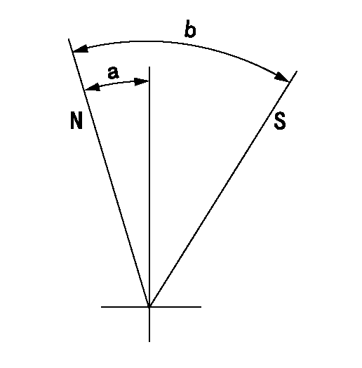
N:Pump normal
S:Stop the pump.
----------
----------
a=5.5deg+-5deg b=39.5deg+-5deg
----------
----------
a=5.5deg+-5deg b=39.5deg+-5deg
Timing setting

(1)Pump vertical direction
(2)Coupling's key groove position at No 1 cylinder's beginning of injection
(3)-
(4)-
----------
----------
a=(30deg)
----------
----------
a=(30deg)
Information:
Table 1
Part Number Part Description Qty
378-3187 Diesel Exhaust Fluid Filter Gp 1
423-3251 Connector 1
391-5262 Gasket 1
425-0385 Filter As 1
452-6055 Filter Base As 1
453-1604(1) Diesel Exhaust Fluid Filter Gp 1
453-1605(1) Diesel Exhaust Fluid Filter Gp 1
453-1606(1) Diesel Exhaust Fluid Filter Gp 1
(1) Use Table 2 to choose the correct part that corresponds to the DEF heater
Table 2
DEF Heater Part Number Required DEF Filter
434-3241 453-1604
434-3242 453-1605
434-3243 453-1606 The effective serial numbers for this change are related to the Pump Electronic Tank Unit (PETU) serial numbers and not the machine serial numbers. Table 3 contains the effective serial numbers for the PETU tank. Refer to illustration 1 and illustration 2 for examples of where to locate the PETU serial number.
Illustration 1 g06018843
Typical example
(1) The location of the PETU serial plate.
Illustration 2 g03418749
Typical example
Table 3
PETU Effective Serial Numbers
S/N:PET007086T-UP Refer to Special Instruction, M0066142, A New Diesel Exhaust Fluid Filter is Now Available for C7.1 Engines for installation instructions.
Have questions with 106661-0936?
Group cross 106661-0936 ZEXEL
Nissan-Diesel
Nissan-Diesel
106661-0936
9 400 616 587
1670096608
INJECTION-PUMP ASSEMBLY
PE6T
PE6T