Information injection-pump assembly
BOSCH
9 400 616 586
9400616586
ZEXEL
106661-0926
1066610926
NISSAN-DIESEL
1671396607
1671396607

Rating:
Service parts 106661-0926 INJECTION-PUMP ASSEMBLY:
1.
_
7.
COUPLING PLATE
8.
_
9.
_
11.
Nozzle and Holder
1660096505
12.
Open Pre:MPa(Kqf/cm2)
22.6(230)
15.
NOZZLE SET
Include in #1:
106661-0926
as INJECTION-PUMP ASSEMBLY
Cross reference number
BOSCH
9 400 616 586
9400616586
ZEXEL
106661-0926
1066610926
NISSAN-DIESEL
1671396607
1671396607
Zexel num
Bosch num
Firm num
Name
106661-0926
9 400 616 586
1671396607 NISSAN-DIESEL
INJECTION-PUMP ASSEMBLY
PE6T K 14CA INJECTION PUMP ASSY PE6P,6PD PE
PE6T K 14CA INJECTION PUMP ASSY PE6P,6PD PE
Calibration Data:
Adjustment conditions
Test oil
1404 Test oil ISO4113 or {SAEJ967d}
1404 Test oil ISO4113 or {SAEJ967d}
Test oil temperature
degC
40
40
45
Nozzle and nozzle holder
105780-8140
Bosch type code
EF8511/9A
Nozzle
105780-0000
Bosch type code
DN12SD12T
Nozzle holder
105780-2080
Bosch type code
EF8511/9
Opening pressure
MPa
17.2
Opening pressure
kgf/cm2
175
Injection pipe
Outer diameter - inner diameter - length (mm) mm 8-3-600
Outer diameter - inner diameter - length (mm) mm 8-3-600
Overflow valve
132424-0620
Overflow valve opening pressure
kPa
157
123
191
Overflow valve opening pressure
kgf/cm2
1.6
1.25
1.95
Tester oil delivery pressure
kPa
157
157
157
Tester oil delivery pressure
kgf/cm2
1.6
1.6
1.6
Direction of rotation (viewed from drive side)
Right R
Right R
Injection timing adjustment
Direction of rotation (viewed from drive side)
Right R
Right R
Injection order
1-4-2-6-
3-5
Pre-stroke
mm
3.2
3.15
3.25
Beginning of injection position
Drive side NO.1
Drive side NO.1
Difference between angles 1
Cal 1-4 deg. 60 59.5 60.5
Cal 1-4 deg. 60 59.5 60.5
Difference between angles 2
Cyl.1-2 deg. 120 119.5 120.5
Cyl.1-2 deg. 120 119.5 120.5
Difference between angles 3
Cal 1-6 deg. 180 179.5 180.5
Cal 1-6 deg. 180 179.5 180.5
Difference between angles 4
Cal 1-3 deg. 240 239.5 240.5
Cal 1-3 deg. 240 239.5 240.5
Difference between angles 5
Cal 1-5 deg. 300 299.5 300.5
Cal 1-5 deg. 300 299.5 300.5
Injection quantity adjustment
Adjusting point
A
Rack position
12.3
Pump speed
r/min
650
650
650
Average injection quantity
mm3/st.
164.2
162.2
166.2
Max. variation between cylinders
%
0
-4
4
Basic
*
Fixing the lever
*
Boost pressure
kPa
37.3
37.3
Boost pressure
mmHg
280
280
Injection quantity adjustment_02
Adjusting point
B
Rack position
6+-0.5
Pump speed
r/min
225
225
225
Average injection quantity
mm3/st.
9.1
8.1
10.1
Max. variation between cylinders
%
0
-10
10
Fixing the rack
*
Boost pressure
kPa
0
0
0
Boost pressure
mmHg
0
0
0
Boost compensator adjustment
Pump speed
r/min
300
300
300
Rack position
10.5
Boost pressure
kPa
6.7
4
6.7
Boost pressure
mmHg
50
30
50
Boost compensator adjustment_02
Pump speed
r/min
300
300
300
Rack position
13
Boost pressure
kPa
24
24
24
Boost pressure
mmHg
180
180
180
Timer adjustment
Pump speed
r/min
925
Advance angle
deg.
0.5
Timer adjustment_02
Pump speed
r/min
1000
Advance angle
deg.
0.8
0.3
1.3
Timer adjustment_03
Pump speed
r/min
1100
Advance angle
deg.
2
1.5
2.5
Remarks
Finish
Finish
Test data Ex:
Governor adjustment
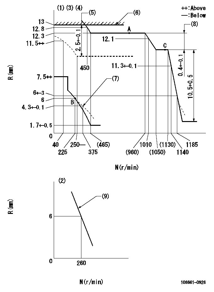
N:Pump speed
R:Rack position (mm)
(1)Adjust with speed control lever at full position (minimum-maximum speed specification)
(2)Adjust with the load control lever in the full position (variable speed specification).
(3)Tolerance for racks not indicated: +-0.05mm.
(4)Deliver with idle sub-spring not operating.
(5)Boost compensator stroke
(6)Rack limit using stop lever
(7)Damper spring setting
(8)Rack difference between N = N1 and N = N2
(9)Main spring setting
----------
N1=1100r/min N2=650r/min
----------
----------
N1=1100r/min N2=650r/min
----------
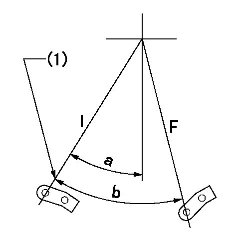
Speed control lever angle

F:Full speed
I:Idle
(1)Stopper bolt setting
----------
----------
a=10deg+-5deg b=(23deg)+-5deg
----------
----------
a=10deg+-5deg b=(23deg)+-5deg
0000000901
F:Full load
I:Idle
(1)Stopper bolt setting
----------
----------
a=32.5deg+-5deg b=38deg+-3deg
----------
----------
a=32.5deg+-5deg b=38deg+-3deg
Stop lever angle
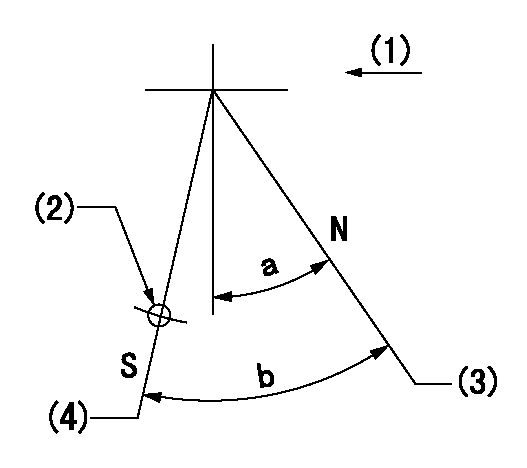
N:Pump normal
S:Stop the pump.
(1)Drive side
(2)Use the hole at R = aa
(3)Rack position bb
(4)Rack position = cc
----------
aa=50mm bb=13mm cc=1.5+-0.1mm
----------
a=32deg+-5deg b=34deg+-5deg
----------
aa=50mm bb=13mm cc=1.5+-0.1mm
----------
a=32deg+-5deg b=34deg+-5deg
Timing setting

(1)Pump vertical direction
(2)Coupling's key groove position at No 1 cylinder's beginning of injection
(3)-
(4)-
----------
----------
a=(30deg)
----------
----------
a=(30deg)
Information:
Introduction
The permanent solution for the problem that is identified below is not known. Until the permanent solution is known, use the solution that is identified below.Problem
The above listed serial numbers have had issues with metal shavings in the Hydraulic Electronic Unit Injector (HEUI) oil passages. These shavings were left in the HEUI oil passages as a result of a nozzle that was not operating correctly.Solution
Return 0R-8849 Cylinder Head Gp with date codes 09006 through date code 12006. Return the 0R-7907 Cylinder Block Gp with the following sequence numbers.
Table 1
Sequence Numbers
01650 01649 01648 01647 01646
01645 01644 01642 01641 01636
01635 01630 01628 01627 01626
01625 01618 01617 01614 01613
01610 01609 01608 01607 01606
01605 01603 01602 01600 01599
01598 01597 01595 01592 Note: If cylinder blocks or cylinder heads have been installed, do not replace the cylinder heads. Instead, flush the HEUI oil system and replace all of the fuel injectors.
Have questions with 106661-0926?
Group cross 106661-0926 ZEXEL
Nissan-Diesel
Nissan-Diesel
106661-0926
9 400 616 586
1671396607
INJECTION-PUMP ASSEMBLY
PE6T
PE6T