Information injection-pump assembly
ZEXEL
106661-0923
1066610923
Rating:
Cross reference number
ZEXEL
106661-0923
1066610923
Zexel num
Bosch num
Firm num
Name
Calibration Data:
Adjustment conditions
Test oil
1404 Test oil ISO4113 or {SAEJ967d}
1404 Test oil ISO4113 or {SAEJ967d}
Test oil temperature
degC
40
40
45
Nozzle and nozzle holder
105780-8140
Bosch type code
EF8511/9A
Nozzle
105780-0000
Bosch type code
DN12SD12T
Nozzle holder
105780-2080
Bosch type code
EF8511/9
Opening pressure
MPa
17.2
Opening pressure
kgf/cm2
175
Injection pipe
Outer diameter - inner diameter - length (mm) mm 8-3-600
Outer diameter - inner diameter - length (mm) mm 8-3-600
Overflow valve
132424-0620
Overflow valve opening pressure
kPa
157
123
191
Overflow valve opening pressure
kgf/cm2
1.6
1.25
1.95
Tester oil delivery pressure
kPa
157
157
157
Tester oil delivery pressure
kgf/cm2
1.6
1.6
1.6
Direction of rotation (viewed from drive side)
Right R
Right R
Injection timing adjustment
Direction of rotation (viewed from drive side)
Right R
Right R
Injection order
1-4-2-6-
3-5
Pre-stroke
mm
3.2
3.15
3.25
Beginning of injection position
Drive side NO.1
Drive side NO.1
Difference between angles 1
Cal 1-4 deg. 60 59.5 60.5
Cal 1-4 deg. 60 59.5 60.5
Difference between angles 2
Cyl.1-2 deg. 120 119.5 120.5
Cyl.1-2 deg. 120 119.5 120.5
Difference between angles 3
Cal 1-6 deg. 180 179.5 180.5
Cal 1-6 deg. 180 179.5 180.5
Difference between angles 4
Cal 1-3 deg. 240 239.5 240.5
Cal 1-3 deg. 240 239.5 240.5
Difference between angles 5
Cal 1-5 deg. 300 299.5 300.5
Cal 1-5 deg. 300 299.5 300.5
Injection quantity adjustment
Adjusting point
A
Rack position
12.3
Pump speed
r/min
650
650
650
Average injection quantity
mm3/st.
164.2
162.2
166.2
Max. variation between cylinders
%
0
-4
4
Basic
*
Fixing the lever
*
Boost pressure
kPa
32
32
Boost pressure
mmHg
240
240
Injection quantity adjustment_02
Adjusting point
B
Rack position
6+-0.5
Pump speed
r/min
225
225
225
Average injection quantity
mm3/st.
9.1
8.1
10.1
Max. variation between cylinders
%
0
-10
10
Fixing the rack
*
Boost pressure
kPa
0
0
0
Boost pressure
mmHg
0
0
0
Boost compensator adjustment
Pump speed
r/min
300
300
300
Rack position
10.5
Boost pressure
kPa
6.7
4
6.7
Boost pressure
mmHg
50
30
50
Boost compensator adjustment_02
Pump speed
r/min
300
300
300
Rack position
13
Boost pressure
kPa
18.7
18.7
18.7
Boost pressure
mmHg
140
140
140
Timer adjustment
Pump speed
r/min
975--
Advance angle
deg.
0
0
0
Remarks
Start
Start
Timer adjustment_02
Pump speed
r/min
925
Advance angle
deg.
0.5
Timer adjustment_03
Pump speed
r/min
1000
Advance angle
deg.
0.8
0.3
1.3
Timer adjustment_04
Pump speed
r/min
1100
Advance angle
deg.
2
1.5
2.5
Remarks
Finish
Finish
Test data Ex:
Governor adjustment
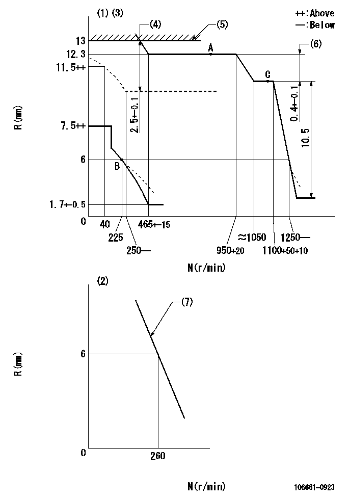
N:Pump speed
R:Rack position (mm)
(1)Maximum - minimum speed specification (using speed lever at adjustment)
(2)Variable speed specification (load control lever at full position)
(3)Beginning of damper spring operation: DL
(4)Boost compensator stroke
(5)Rack limit using stop lever
(6)Rack difference between N = N1 and N = N2
(7)Main spring setting
----------
DL=4.8-0.2mm N1=1100r/min N2=650r/min
----------
----------
DL=4.8-0.2mm N1=1100r/min N2=650r/min
----------
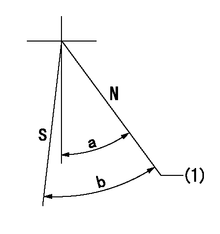
Speed control lever angle
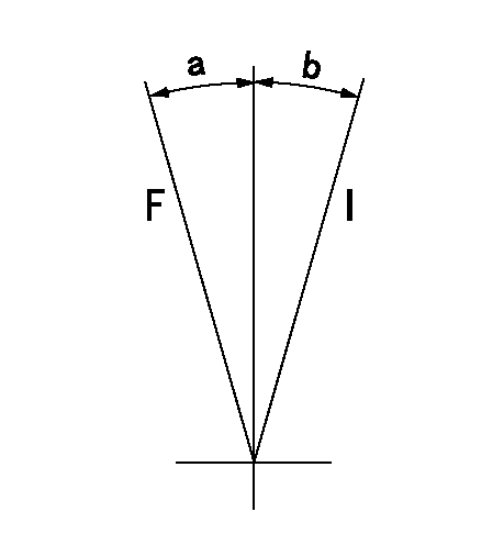
F:Full speed
I:Idle
----------
----------
a=10deg+-5deg b=(13deg)+-5deg
----------
----------
a=10deg+-5deg b=(13deg)+-5deg
0000000901
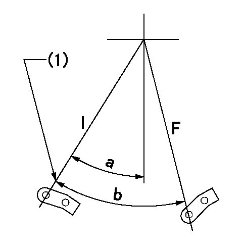
F:Full load
I:Idle
(1)Stopper bolt setting
----------
----------
a=32.5deg+-5deg b=38deg+-3deg
----------
----------
a=32.5deg+-5deg b=38deg+-3deg
Stop lever angle
N:Pump normal
S:Stop the pump.
(1)Rack position = aa
----------
aa=13mm
----------
a=32deg+-5deg b=34deg+-5deg
----------
aa=13mm
----------
a=32deg+-5deg b=34deg+-5deg
Timing setting

(1)Pump vertical direction
(2)Coupling's key groove position at No 1 cylinder's beginning of injection
(3)-
(4)-
----------
----------
a=(30deg)
----------
----------
a=(30deg)
Information:
Introduction
Injector height setting is extremely important during the engine assembly process. The recommended intervals that are specified in the Operation and Maintenance Manual must be followed.Problem
An issue has been identified with the correct injector height settings. Check the injector height. Bottoming of the fuel injector rocker arm may be caused by the injector height being to high or low. Bottoming of the fuel injector can create a crack at the nose of the fuel injector rocker arm through the first and second threads of the adjusting screw hole. Once the crack has started it can result in the breaking of the fuel injector rocker arm at the nose. Breaking of the fuel injector rocker arm will result in an immediate poor engine performance.Solution
Performing the recommended inspection of the fuel injector rocker arm at the specified intervals in the operation and maintenance manual is important. Inspect the height